M
O
N
T
A
G
E
GB
FR
DE
Wärmeerzeugung par excellence
L
I
U
QAA 73-BAUSATZ RAUMENDGERÄT
ZEM
Z
-33-0
REG 74
- W09.36751 -
T30.36754.01
Page 1: ...N O T I C E M O N T A G E E D la chaleur haute fid lit GB DE FR KIT TERMINAL D AMBIANCE QAA 73 ZEM ZEM 33 0 T30 36754 01 REG 74 W09 36751...
Page 2: ...CE ET DES ACCESSOIRES 4 III UTILISATION PARAMETRAGES 7 1 UTILISATION DE LA QAA 73 7 2 NIVEAU 1 PARAMETRAGE PAR L UTILISATEUR FINAL 7 3 NIVEAU 2 PARAMETRAGE PAR LE CHAUFFAGISTE 8 4 LISTE DES PARAMETRES...
Page 3: ...ge Protection hors gel du b timent Programme de vacances Affichage en clair dans diff rentes langues au choix Outil de r glage des diff rents param tres du LMU34 pour l installateur Acc s diff rentes...
Page 4: ...ongueur maximale du c ble L 50 m Le c ble reliant la sonde l unit centrale de gestion LMU ne sera pas pos en parall le ni dans la m me gaine que les c bles lectri ques 230 V cart 30 cm minimum conseil...
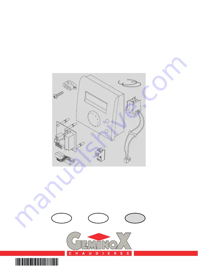
Page 5: ...00 de la carte LMU de la chau di re clipser l AGU 2 1 sur la carte LMU de la chaudi re raccorder le connecteur 2 pts 3 1 du fais ceau de raccordement 3 sur les bornes 7 et 8 de l AGU 2 1 clipser le co...
Page 6: ...ambiance QAA 73 au tableau de commande l aide du serre c ble 5 Pour le march fran ais uniquement ter le connecteur 2 pts 16 et son shunt de la borne TT du tableau de commande la consigne chauffage se...
Page 7: ...1 Affichage 2 A l aide des touches de s lection de ligne choisissez la ligne voulue rep b Les possibilit s de r glage sont indiqu es au 4 1 page 9 chapitre III UTILISATION PARAMETRAGEs 3 R gler la va...
Page 8: ...chauffagiste niveau 2 Affichage 3 A l aide des touches de s lection de ligne choisissez la ligne voulue rep b toutes les lignes possibles figurent au 4 2 page 11 chapitre III UTILISATION PARAMETRAGEs...
Page 9: ...00 00 24 00 hh mn 10 min 14 Heure d arr t 2 me phase 00 00 24 00 hh mn 10 min 15 Heure d enclenchement 3 me phase 00 00 24 00 hh mn 10 min 16 Heure d arr t 3 me phase 00 00 24 00 hh mn 10 min Program...
Page 10: ...ois inactif 1er jan 31 d c jj mm 1 jour 41 Fin cong s jour mois inactif 1er jan 31 d c jj mm 1 jour 42 Niveau de fonct du CC pendant les vacances hors gel conomie hors gel G n ralit s 45 Retour aux pr...
Page 11: ...laire 40 250 C 1 61 Temp mesur e de l accumulateur solaire 40 127 C 1 62 Mode OpenTherm Lite Plus 63 Consigne de d part effective CC 1 0 100 C 1 64 Consigne de d part effective CC 2 0 100 C 1 Chauffag...
Page 12: ...5 4 5 K 0 5 0 0 Eau Chaude Sanitaire 90 Consigne de temp d conomie pour l ECS TBWR 8 TBWw C 1 40 91 Autorisation de la charge d eau chaude sanitaire 24h jour ZSP 1 CC 1h ZSP CC ZSP ECS 24 h jour 92 Fo...
Page 13: ...High fidelity heat I N S T A L I N S T R U A L T C T I O N I O N S DE FR GB ROOM SENSOR KIT QAA 73 ZEM ZEM 33 0 T30 36754 01 REG 74 W09 36751...
Page 14: ...M SENSOR AND ACCESSORIES 4 III USING SETTINGS 7 1 USING THE QAA 73 7 2 1 LEVEL PARAMETER SETTINGS FOR THE END USER 7 3 2 LEVEL PARAMETER SETTINGS FOR THE HEATING ENGINEER 8 4 PARAMETER LIST QAA73 STOR...
Page 15: ...and clock waiver buttons Anti freeze protection for the building Holiday programme Clear display in a choice of different lan guages Installer s tool to adjust the different LMU34 parameters Access to...
Page 16: ...le must be used Maximum length of cable L 50 m The cable connecting the sensor to the LMU management unit mut not be laid in parallel or in the same ca bleway as the 230 V electrical ca bles minimum d...
Page 17: ...minal X300 of the boiler s LMU board Clip the AGU 2 1 to the boiler s LMU board Connect the 2 pin connector 3 1 of the connection wires 3 to terminals 7 and 8 of the AGU 2 1 Clip the 2 pin connector 3...
Page 18: ...e cable runs on the boiler body the ca ble run cutout must be adapted to the diam eter of the cable used Connect the 2 pin connector 4 to the QAA 73 room sensor cable then connect it to the QAA termin...
Page 19: ...lection buttons to select the required line rep b The parameter list containing all possible settings is indicated in Section 4 1 page 9 chapter III USING SETTINGS 3 Press the plus or minus button to...
Page 20: ...evel Display 3 Press the line selection buttons to select the required line rep b All possible lines are indicated in Section 4 2 page 11 chapter III USING SETTINGS 4 Press the plus or minus button to...
Page 21: ...e 00 00 24 00 hh mn 10 min 14 switch off time 2nd phase 00 00 24 00 hh mn 10 min 15 switch on time 3rd phase 00 00 24 00 hh mn 10 min 16 switch off time 3rd phase 00 00 24 00 hh mn 10 min Time switch...
Page 22: ...t day month inactif 1 jan 31 dec tt mm 1 day 41 Holidays end day month inactif 1 jan 31 dec tt mm 1 day 42 Heating circuit operating level during holidays Frost reduced Frost General 45 STANDARD time...
Page 23: ...61 Actual temperature of solar storage tank 40 127 C 1 62 OpenTherm mode Lite Plus 63 Current flow temperature setpoint HC1 0 100 C 1 64 Current flow temperature setpoint HC2 0 100 C 1 Space heating H...
Page 24: ...hot water 90 Reduced setpoint of d h w temperature TBWR 8 TBWw C 1 40 91 Release of d h w heating 24h day TSP 1 HC 1h TSP HC TSP D H W 24 h day 92 Legionella function Off on on 93 Operating mode of d...
Page 25: ...M O N T A G E GB FR DE W rmeerzeugung par excellence A N L E I T U N G QAA 73 BAUSATZ RAUMENDGER T ZEM ZEM 33 0 REG 74 W09 36751 T30 36754 01...
Page 26: ...S UND DER ZUBEH RTEILE 4 III EINSATZ PARAMETRIERUNG 7 1 EINSATZ DES QAA 73 7 2 1 BEDIENEBENE PARAMETRIERUNG ENDBENUTZER 7 3 2 BEDIENEBENE PARAMETRIERUNG HEIZUNGSFACHMANN 8 4 PARAMETERLISTE QAA73 GESPE...
Page 27: ...s bersteuerung und Uhrzeiteinstellung Geb udefrostschutz Urlaubsprogramm Gut lesbare Anzeige in mehreren Sprachen Vorrichtung f r die Einstellung der LMU34 Parameter durch den Installateur Info Taste...
Page 28: ...ormtes Kabel 2 x 1 5 mm ve rwenden Maximale Kabell nge L 50 m Das Kabel zwischen F hler und BMU darf weder parallel noch im gleichen Kabelkanal wie das 230 V Netzkabel verlegt werden empfo hlener Mind...
Page 29: ...300 der Kessel BMU anschlie en Den AGU 2 1 auf der Karte der Kessel BMU festklipsen Den 2 poligen Stecker 3 1 des Anschluss kabelb ndels 3 an die AGU Klemmen 7 und 8 2 1 anschlie en Den 2 poligen Stec...
Page 30: ...run gen des Kesselgestells f hren Ausschnitt der Kabeldurchf hrung muss auf den Durch messer des verwendeten Kabels abstim men Den 2 poligen Stecker 4 zun chst an das Kabel des Raumtemperaturger ts QA...
Page 31: ...n Sie mit den Zeilenwahl Tasten die entsprechende Zeile an rep b Die Einstellungsm glichkeiten sind in Abschn 4 1 Seite 9 Kapitel III EINSATZ PARAMETRIERUNG dargestellt 3 Stellen Sie den gew nschten W...
Page 32: ...ann 2 Bedienebene Anzeige 3 W hlen Sie mit den Zeilenwahl Tasten die entsprechende Zeile an rep b Die m glichen Zeilen sind in Abschn 4 2 Seite 11 Kapitel III EINSATZ PARAMETRIERUNG dargestellt 4 Stel...
Page 33: ...00 hh mn 10 min 16 Zeitschaltprogramm HK 1 Ausschaltzeit 3 Phase 00 00 24 00 hh mn 10 min Zeitschaltprogramm HK 2 Heizkreis 2 20 Zeitschaltprogramm HK 2 Wochentag Vorwahl Mo So Woche Tag 1 Tag 21 Zei...
Page 34: ...41 Ferienende Tag Monat inaktiv 1 Jan 31 Dez tt mm 1 Tag 42 Heizkreisbetriebsniveau w hrend Ferien Frost Reduziert Frost Allgemein 45 STANDARD Zeitschaltprogramme f r HK 1 2 und BW Doppeltastendruck...
Page 35: ...tur Istwert 40 250 C 1 61 Solar Speichertemperatur Istwert 40 127 C 1 62 OpenTherm Modus Lite Plus 63 Aktueller Vorlauftemperatur Sollwert HK1 0 100 C 1 64 Aktueller Vorlauftemperatur Sollwert HK2 0 1...
Page 36: ...iebung Heizkennlinie HK2 4 5 4 5 K 0 5 0 0 Brauchwasser 90 Brauchwassertemperatur Reduziertsollwert TBWR 8 TBWw C 1 40 91 Freigabe der Brauchwasserladung 24h Tag ZSP 1 HK 1h ZSP HK ZSP BW 24 h Tag 92...
Page 37: ...NOTIZEN 13...
Page 38: ...NOTIZEN 14...
Page 39: ...NOTIZEN 15...
Page 40: ...GEMINOX SAS 16 rue des Ecoles BP 1 29410 SAINT THEGONNEC FRANCE Internet http www geminox fr Document non contractuel Non contractual document Unverbindliche Dokumentation F VRIER 2007...