Gemini CS-02 User Manual Download Page 6

15. 

G

ROUND

L

IFT

S

WITCH

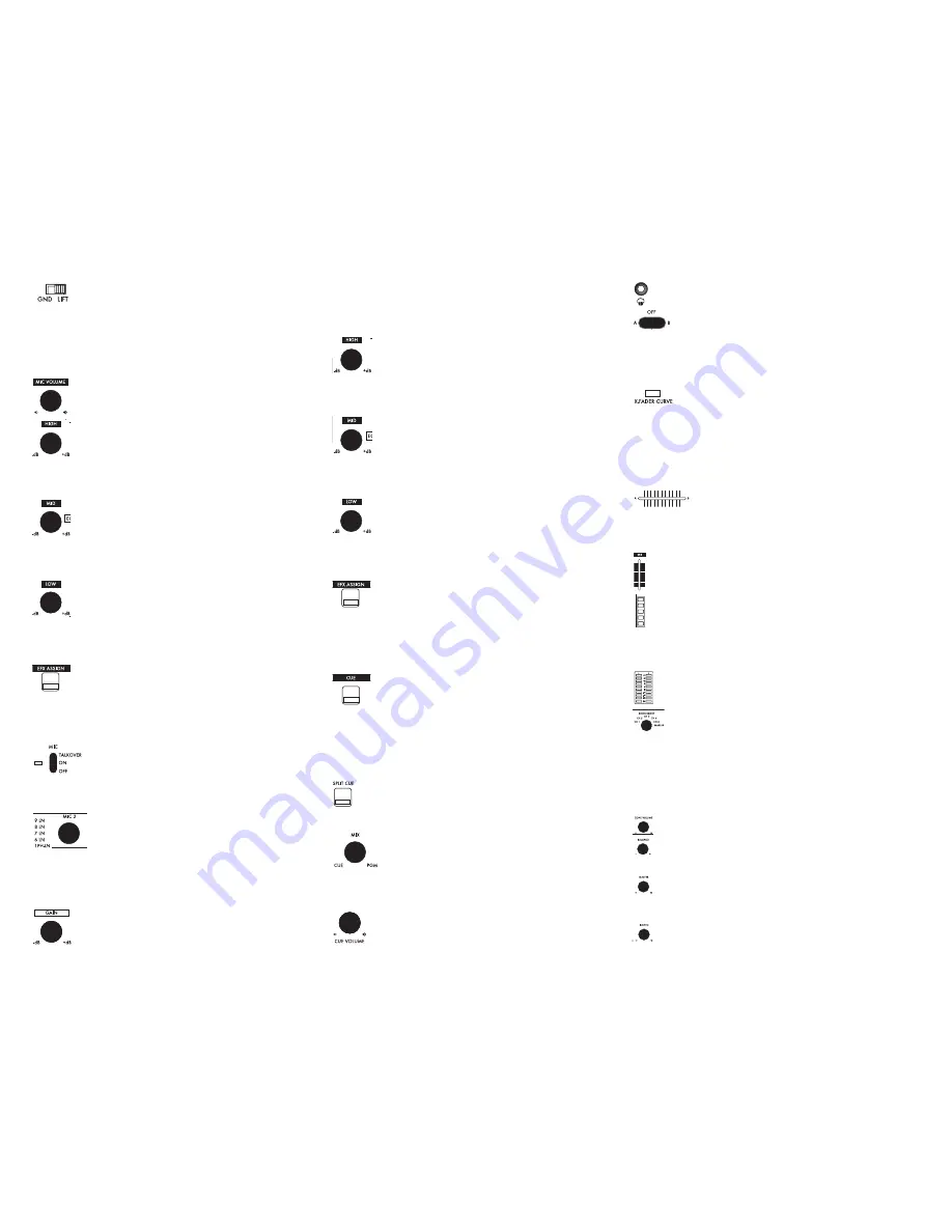
(56): This switch lifts the signal ground,

and may help in the event of a stubborn ground loop issue.

Using the 

G

ROUND

L

IFT

S

WITCH

is in no way a substitute for proper wiring,

but in a live scenario, it can help to eliminate ground hum. Before chang-
ing the position of the switch, make sure to turn the unit 

Off. 

If both ‘

GND

and ‘

LIFT

’ settings sound identical, then keep the switch set to ‘

GND

’. 

FUNCTIONS:

1. 

M

IC

V

OLUME

(2): This rotary control alters the volume of the

Microphone that is plugged into the 

XLR-1/4” C

OMBO

M

IC

1 I

NPUT

(1). 

2. 

M

IC

1 H

IGH

B

AND

EQ 

(3): This rotary control alters the amount

of high frequency that is applied to Microphone #1. Turning the
control clockwise increases the high frequencies, while turning

the control counterclockwise decreases. In the middle position (the rotary
control is detented here), there is no change being made to the audio sig-
nal.

3. 

M

IC

1 M

ID

B

AND

EQ 

(4): This rotary control alters the amount

of midrange frequency that is applied to Microphone #1.
Turning the control clockwise increases the midrange frequen-

cies, while turning the control counterclockwise decreases. In the middle
position (the rotary control is detented here), there is no change being
made to the audio signal.

4.

M

IC

1 L

OW

B

AND

EQ 

(5): This rotary control alters the amount

of low frequency that is applied to Microphone #1. Turning the
control clockwise increases the low frequencies, while turning

the control counterclockwise decreases. In the middle position (the rotary
control is detented here), there is no change being made to the audio sig-
nal.

5. 

M

IC

1 EFX A

SSIGN

B

UTTON

(6): This button assigns the audio

signal of Microphone #1 to the DSP EFX section found on this
mixer. When the LED on this button is illuminated, it indicates

that the signal is being fed through the DSP. When the LED on this button
is extinguished, it indicates that the signal is being output as-is, without any
effect.

6. 

M

IC

1 O

N

/O

FF

/T

ALKOVER

S

WITCH

(7): This switch determines

whether Microphone #1 will be on, off, or on with Talkover.
When talkover is engaged, the level of the audio (except for

the microphone) will be attenuated so that the microphone can be easily
heard over any music that may be playing. 

7. 

D

EVICE

/C

HANNEL

A

SSIGN

K

NOB

(8): This control, which is

found on each mixer channel, determines which set of jacks
will be used to drive that channel. Printed next to the knob

itself is a diagram showing the positions and available devices that can be
assigned to the channel. This feature allows many devices to be connected,
5 of which can be used simultaneously when they are selected using the

D

EVICE

/C

HANNEL

A

SSIGN

K

NOB

s.

8. 

C

HANNEL

G

AIN

C

ONTROL

(9): These controls, found on each

mixer channel, allow you to increase or decrease the volume of
each channel. This is useful for matching levels during mixing,

or to make additional signal boosts when the 

C

HANNEL

V

OLUME

F

ADERS

(22)

do not provide enough. To match levels while mixing, visually match the
level of the 

C

HANNEL

LED VU M

ETERS

(23), by making adjustments to the

C

HANNEL

G

AIN

C

ONTROLS

9. 

C

HANNEL

H

IGH

B

AND

EQ 

(10): This rotary control, found on

each channel, alters the amount of high frequency that is applied
to the corresponding channel. Turning the control clockwise

increases the high frequencies, while turning the control counterclockwise
decreases. In the middle position (the rotary control is detented here),
there is no change being made to the audio signal.

10. 

C

HANNEL

M

ID

B

AND

EQ 

(11): This rotary control, found on

each channel, alters the amount of midrange frequency that is
applied to the corresponding channel. Turning the control

clockwise increases the midrange frequencies, while turning the control
counterclockwise decreases. In the middle position (the rotary control is
detented here), there is no change being made to the audio signal.

11.

C

HANNEL

L

OW

B

AND

EQ 

(12): This rotary control, found on

each channel, alters the amount of low frequency that is applied
to the corresponding channel. Turning the control clockwise

increases the low frequencies, while turning the control counterclockwise
decreases. In the middle position (the rotary control is detented here),
there is no change being made to the audio signal.

12. 

C

HANNEL

EFX A

SSIGN

B

UTTON

(13): When these buttons,

found on each channel, are pressed, the audio which corre-
sponds to that channel is routed to the DSP effects section. When

C

HANNEL

EFX A

SSIGN

B

UTTON

is active, the LED inside of the button will

illuminate. Only one channel at a time can be assigned to the DSP effects.
When there is no 

C

HANNEL

EFX A

SSIGN

B

UTTON

active, the 

Master

bus will

be sent through the DSP effects section.

13. 

C

HANNEL

CUE S

ELECTOR

(14): These buttons, found on each

channel, route the pre-fader audio signal to the 

Cue Section

,

which can be monitored through headphones.  This is useful for

playing a particular piece of music through the headphones while there is
another music program playing through the speakers. When a 

C

HANNEL

CUE S

ELECTOR

B

UTTON

is active, the LED inside of the button will illumi-

nate. You may choose as many channels as you wish, simultaneously, to be
monitored through the 

Cue Section.

14. 

S

PLIT

C

UE

B

UTTON

(15): The 

Split Cue

function allows you to

monitor sound from the 

Cue Section 

in one ear, while listening to

the 

Program 

(Master Bus) in the other ear. This is particularly use-

ful if there is no booth monitor available, or if the monitor is unusable.

15. 

CUE/PGM R

OTARY

C

ONTROL

(16): When this rotary control

is all the way to the left, only the 

Cue Section 

will be heard

through the headphones. When this rotary control is all the

way to the right, only the 

Program 

(Master Bus) will be heard through

the headphones. When this control is in the middle, an equal mix of 

Cue

and 

PGM.

16. 

C

UE

V

OLUME

C

ONTROL

(17): This controls the volume of the

H

EADPHONE

O

UTPUT

(18).

17. 

H

EADPHONE

O

UTPUT

(18)

This jack accepts a standard 1/4”

(6.35mm) connector, and will power virtually any headphones.

18. 

X-F

ADER

A

SSIGN

S

WTICH

(19): These switches, which are

found on each channel, are used to assign each respective

audio channel to either the left side (A) or the right side (B) of the 

X-

F

ADER

(21). When the switch is in the middle position (

Off )

, the audio of

each channel will be controlled solely by the 

C

HANNEL

V

OLUME

F

ADER

(22),

and not by the 

X-F

ADER

(21).

19. 

X-F

ADER

C

URVE

S

WITCH

(20): This switch determines the

taper of the 

X-F

ADER

(21). When the switch is set to the left

(gradual taper), the 

X-F

ADER

(21) will have a smooth and gradual

response which is best suited towards mixing. When the switch is set to
the right (short taper), the 

X-F

ADER

(21) will have a sharper response

which is best suited towards scratch and battle use. For an even sharper
response, replace the stock fader with an 

RG-45PRO Scratch Fader

(sold

separately).

20. 

X-F

ADER

(21): With this control, you can fade between

all of the active channels that are assigned to the ‘

A

’ side

of the 

X-F

ADER

and the active channels that are assigned to the ‘

B

’ side of

the 

X-F

ADER

. Assigning channels to the 

X-F

ADER

is accomplished using the

X-F

ADER

A

SSIGN

S

WTICHES

(19).

21. 

C

HANNEL

V

OLUME

F

ADER

(22): These controls, found on each chan-

nel, allow you to control the amount of signal that is sent to the out-
put of the mixer.
23. 

C

HANNEL

LED VU M

ETER

(23): This VU meter displays the prefader

level of the audio source. This has a multitude of uses, such as visually
verifying which channels are receiving audio signal or matching the

volume levels between two sources. For optimal sound, you should adjust
the 

C

HANNEL

G

AIN

C

ONTROLS

(9) until the 

C

HANNEL

LED VU M

ETER

begins

to light the first blue 

LED

.

24. 

M

ASTER

LED VU M

ETER

(24): This VU meter displays the level of

the signal being output through the 

M

ASTER

O

UTPUTS

of the mixer.

For optimal sound, this should not 5dB on the meter.

25. 

Z

ONE

S

ELECT

C

ONTROL

(25): By using this control, you can

select a source to be output directly to the 

Z

ONE

RCA O

UTPUTS

(64) found on the rear panel of the mixer. The audio signal output will be
completely prefader, which means that the 

C

HANNEL

V

OLUME

F

ADER

(22)

has no effect on the level of the output. However, the audio will still be
affected by the 

C

HANNEL

G

AIN

C

ONTROL

(9) and 

C

HANNEL

EQ

S

(10, 11, 12).

When the 

Z

ONE

S

ELECT

C

ONTROL

is set to 

Master

, the 

Z

ONE

RCA O

UTPUTS

(64) will behave the same as the 

B

OOTH

RCA O

UTPUTS

(63).

26. 

Z

ONE

V

OLUME

(26): This rotary control determines the volume of

the audio being sent out through the 

Z

ONE

RCA O

UTPUTS

(64).

27. 

B

ALANCE

C

ONTROL

(29): This control allows you to pan the

Master 

signal from Left to Right. By default, this control should be

in the middle position, which is an equal balance of left and right chan-

nels.

28. 

M

ASTER

V

OLUME

C

ONTROL

(30): This rotary control determines

the volume of the audio being sent out through the 

M

ASTER

O

UTPUTS

(59,

60).

29. 

B

OOTH

V

OLUME

C

ONTROL

(31): This rotary control determines the

volume of the audio being sent out through the 

B

OOTH

RCA

<6>

Summary of Contents for CS-02

Page 1: ... be liable for any loss or damage whatsoever arising from the use of information or any error contained in this manual No part of this manual may be reproduced stored in a retrieval system or transmitted in any form or by any means electronic electrical mechanical optical chemical including pho tocopying and recording for any purpose without the express written permission of Gemini Sound Products ...

Page 2: ... by items placed upon or against them paying particular attention to cords at plugs convenience receptacles and the point where they exit from the product OUTDOOR ANTENNA GROUNDING If an outside antenna or cable sys tem is connected to the product be sure the antenna or cable system is grounded so as to provide some protection against voltage surges and built up static charges Article 810 of the N...

Page 3: ...hone Output 19 X Fader Assign Switch 20 X Fader Curve Switch 21 X Fader 22 Channel Volume Fader 23 Channel LED VU Meter 24 Master LED VU Meter 25 Zone Select Control 26 Zone Volume 27 Auxilary RCA Inputs 28 Record RCA Outputs 29 Balance Control 30 Master Volume Control 31 Booth Volume Control 32 Mono Output Switch 33 Auto BPM Tap Button 34 EFX Tempo Sync On Off 35 Tempo Ratio Selector 36 LCD Param...

Page 4: ...7 Input 52 Line 8 Input 53 Line 9 Input 54 Line 10 Input 55 Ground Terminals 56 Ground Lift Switch 57 Mic 2 1 4 Input 58 Mic 3 1 4 Input Output Section 59 Balanced XLR Master Outputs 60 Master RCA Outputs 61 Master Volume Attenuation Switch 62 Record RCA Outputs 63 Booth RCA Outputs 64 Zone RCA Outputs Power Section 65 AC Power Inlet w Fuse 66 Voltage Selection Switch 67 Power Switch 42 44 45 46 4...

Page 5: ... Phono Cable underneath any of the GROUND TERMINALS 55 found on the rear of the mixer 7 XLR 1 4 COMBO MIC 1 INPUT 1 This input is found on the face of the mixer and is used for connecting microphones that are terminated with a 1 4 or XLR connector This input is con trolled solely by the volume and EQ controls found directly below the jack For more information about using these controls see the Fun...

Page 6: ...channel is routed to the DSP effects section When a CHANNEL EFX ASSIGN BUTTON is active the LED inside of the button will illuminate Only one channel at a time can be assigned to the DSP effects When there is no CHANNEL EFX ASSIGN BUTTON active the Master bus will be sent through the DSP effects section 13 CHANNEL CUE SELECTOR 14 These buttons found on each channel route the pre fader audio signal...

Page 7: ...FX ON OFF BUTTON 41 By pressing this button the DSP effect that is selected is turned On or Off REPLACING THE X FADER AND CHANNEL FADERS 1 Remove the black brushed aluminum plate which outlines the Channel and X Fader section The screws can be found at each corner of this plate 2 To remove a channel fader simply remove the two screws on the top and bottom of the fader Disconnect the connector whic...

Page 8: ... darauf stehenden oder gegen sie stoßenden Gegenständen gequetscht werden Achten Sie beson ders auf Kanten Sicherung Stecker und Buchsen AUSSENANTENNENERDUNG Wenn Sie eine Außenantenne oder ein Radio Fernsehkabelsignal an das Produkt anschließen achten Sie darauf dass die Antenne oder das Kabel geerdet sind um dafür zu sorgen dass Überspannungen und elektrostatische Aufladungen nicht auftreten kön...

Page 9: ...g 19 X Fader Zuweis Schalter 20 Crossfader Curve Schalter 21 Crossfader 22 Kanal Fader 23 Kanal LED Pegelanzeige 24 Master LED Pegelanzeige 25 Zone Wahlschalter 26 Zone Lautstärkeregler 27 Auxilary Cinch Eingang 28 Record Cinch Ausgänge 29 Balance Regler 30 Master Lautstärkeregler 31 Booth Lautstärkeregler 32 Mono Schalter 33 Auto BPM Tap Taste 34 EFX Tempo Sync Ein Aus 35 Tempo Ratio Schalter 36 ...

Page 10: ...Eingang 52 Line 8 Eingang 53 Line 9 Eingang 54 Line 10 Eingang 55 Erdungsanschluss 56 Ground Lift Schalter 57 Mic 2 1 4 Eingang 58 Mic 3 1 4 Eingang Ausgangssektion 59 Symmetrischer XLR Master Ausgang 60 Master Cinch Ausgang 61 Master Dämpfungsschalter 62 Record Cinch Ausgang 63 Booth Cinch Ausgang 64 Zone Cinch Ausgang Stromsektion 65 Netzbuchse mit Sicherung 66 Spannungswahlschalter 67 Ein Aus S...

Page 11: ...ießen ist es nötig diese mit dem ERDUNGSANSCHLUSS 55 zu verbinden um Brummen zu unterbinden Schalten Sie den CS 02 aus und führen die Klemme am Erdungskabel in den rückseitigen ERDUNGSANSCHLUSS 55 7 Kombi XLR 6 3 MM KLINKENEINGANG 1 1 An diesen Eingang auf der Oberseite des Mixers können Sie Mikrofone mit 6 3 mm Klinken oder XLR Stecker anschließen Der Eingang wird nur ausschließlich vom Lautstärk...

Page 12: ... Sie in jedem Kanal finden können Sie das Signal bevor es den Fader durch läuft in die Cue Sektion leiten die Sie mit dem Kopfhörer abhören können Das ist nützlich wenn Sie ein Signal nur mit dem Kopfhörer hören wollen während ein anderes über den Master Ausgang abgespielt wird Ist eine KANAL CUE WAHLTASTE aktiv leuchtet die LED in der Taste auf Sie können beliebig viele Kanäle gleichzeitig zum Hö...

Page 13: ...ie einen neuen Fader ein Überprüfen Sie dass der neue Fader richtig herum eingesetzt ist bevor Sie ihn festschrauben 3 Zum Tausch des Crossfaders lösen Sie die beiden äußeren Schrauben des Crossfaders und ziehen Sie den Stecker am Boden des Faders ab Jetzt lösen Sie die beiden inneren Schrauben um die Stahlplatte zu entfernen Setzen Sie die Platte auf den neuen Crossfader RG 45 oder RG 45PRO Nachd...

Page 14: ...pinche los mismos poniendo particular atención en la unión con el conector y en el punto donde se une a la unidad TOMA DE TIERRA DE ANTENA EXTERIOR Si hay conectado a este pro ducto un cable de antena o antena exterior asegúrese de su correcta conexión a tierra para proteger de posibles entradas de tensión y cargas de electricidad estática El Articulo 810 del Código Eléctrico Nacional ANSI NFPA 70...

Page 15: ...res 19 Interrruptor Asign X Fader 20 Interruptor Curva X Fader 21 X Fader 22 Fader Canal Volumen 23 LED VU Canal 24 LED VU Master 25 Control Selección Zona 26 Volumen Zona 27 Entradas Auxiliares RCA 28 Salidas Grabación RCA 29 Control de Balance 30 Control Volumen Master 31 Control Volumen Cabina 32 Interruptor Salida Mono 33 Botón Auto BPM Tap 34 Efectos Tiempo Sinc On Off 35 Selector Tempo 36 Di...

Page 16: ... 53 Line 9 Entrada 54 Line 10 Entrada 55 Terminales de Masa 56 Interruptor Lift de Masa 57 Mic 2 1 4 Entrada 58 Mic 3 1 4 Entrada Sección Salida 59 Salidas Balanceadas XLR Master 60 Salidas Master RCA 61 Inter Atenuación Volumen Master 62 Salidas Grabación RCA 63 Salidas Cabina RCA 64 Salidas Zona RCA Alimentación 65 Corriente AC entrada con Fusible 66 Interruptor Selección Voltaje 67 Interruptor ...

Page 17: ...ndo así zumbidos Con el interruptor en OFF Sencillamente conecte el cable de masa incluido con el Cable de Phono del giradiscos en la TERMINAL DE MASA 55 detrás del mezclador 7 1 ENTRADA DE MICRÓFONO COMBO XLR 1 4 1 Esta entrada se encuentra en la caratula del mezclador y se usa para la conexión de micrófonos con conector de 1 4 o XLR Esta salida esta con trolada exclusivamente por los controles d...

Page 18: ...ual corresponden es conducido a la sección de efectos DSP Cuando el BOTÓN DE ASIGNACIÓN DE EFECTOS DE CANAL es activado el led interno del botón se iluminará Solamente un canal puede tener asignado los efectos DSP Cuando no este activado el trabajo Master se enviará a través de la sección de efectos DSP 13 SELECTOR DE CANAL CUE 14 Estos botones originarios en cada canal trazan el camino a la señal...

Page 19: ...que esta seleccionado estará Encendido o Apagado REEMPLAZAR EL X FADER Y EL CANAL DE FADERS 1 Quitar la placa negra de aluminio raspado que cubre el Canal y sección de X Fader Los tornillos se encuentran en cada esquina de la placa 2 Quitando un fader de canal simplemente quita dos tornillos en la super ficie y el botón del fader Desconecta el conector que esta dentro del botón del fader y cambial...

Page 20: ... Les cordons d alimen tation doivent être déroulés et rangés proprement afin d éviter de se pren dre les pieds dedans en particulier les cordons reliés aux prises élec triques ANTENNE EXTERIEURE Si vous reliez votre appareil à une antenne ou un câble extérieur assurez vous de la présence d une connexion à la terre afin d éviter les surtensions et les décharges d électricité statique L article 810 ...

Page 21: ...tion de la Voie au Crossfader 20 Réglage de Courbe du Crossfader 21 Crossfader 22 Réglage de Volume 23 VU Mètre à Leds 24 VU Mètre Master à Leds 25 Sélection de la Source Assignée à la Sortie Zone 26 Volume Sortie Zone 27 Entrée Stéréo Auxilaire 28 Sortie Enregistrement 29 Balance 30 Réglage Volume Master 31 Réglage Volume Sortie Auxiliaire 32 Commutation Mono 33 BPM Auto BPM manuel 34 Touche On O...

Page 22: ...ise à la Terre 56 Commutateur de Mise à la Terre 57 Micro 2 Jack 6 35mm 58 Micro 3 Jack 6 35mm Sorties 59 Sortie Master Symétrique XLR 60 Sortie Master Asymétrique RCA 61 Atténuation Sortie Master 62 Sortie Enregistrement RCA 63 Sortie Auxiliaire Booth RCA 64 Sortie Zone RCA Alimentation 65 Embase AC avec Fusible 66 Sélection Tension d Alimentation 67 Interrupteur de Mise sous Tension 42 44 45 46 ...

Page 23: ...ra un son inaudible et ou accompagné de distorsion 5 ENTRÉES LIGNE 44 47 50 51 52 53 54 Ces entrées acceptent toute source de niveau ligne Platine lecteur CD 6 VIS DE MISE A LA TERRE Lorsque vous connectez plusieurs platines vinyles avec les ENTRÉES PHONO LIGNE 42 45 48 il est nécessaire d utiliser les VIS DE MASSE 55 pour éliminer tout bruit de ronronnement Avec l alimentation éteinte Power OFF r...

Page 24: ...tre rotatif est situé à gauche vous n entendrez que le signal de la voie sélectionnée en Pré écoute Lorsque ce potentiomètre est situé à droite vous n entendrez que le Programme principal Master bus Lorsque ce potentiomètre est positionné au milieu vous entendrez le son de la Pré écoute le son du Programme principal simultané ment 16 RÉGLAGE VOLUME CASQUE 17 Ce potentiomètre permet de régler le vo...

Page 25: ...r replacez le Crossfader dans son emplacement remettez les vis en place PIÈCES REMPLAÇABLES PAR L UTILISATEUR Vous trouverez ci après la liste des pièces détachées disponibles auprès de votre revendeur Gemini CROSSFADER RG45 OU RG 45PRO FADER DE VOIE 072 127 BOUTON FADER DE VOIE CROSSFADER 002 742 BOUTON FADER PARAMETER CONTROL 002 741 BORNE DE MASSE 146 710 CARACTERISTIQUES TECHNIQUES Entrées Pho...

Page 26: ...irst Name Last Name Province Address Number and Street City Apt Country Postal Code Model Number Example CDT 05 Serial Number Located on back of most units Serial Number Located on back of most units Month Day Year Date of Purchase Month Day Year Date of Purchase Purchase Price 00 EXCLUDING TAX Dealer Zip Code Age City or Month Day Year Date of Birth Model Number Example CDT 05 Save postage and re...

Reviews: