


Cinterion
®
LGA DevKit User Guide
6 Operating DevKit on DSB75 and DSB-Mini
27
lga_devkit_ug_v02
2019-05-27
Preliminary
Page 17 of 28
6
Operating DevKit on DSB75 and DSB-Mini
The LGA DevKit supports a 2x40pin connector at its bottom side, compatible to the DSB75/
DSB-Mini. A DSB may be a port extender for an RS232 interface, a second SIM or an analog
audio interface. When operating the LGA DevKit with a DSB the following settings can be ad-
justed.
•
Use the "PWR" switch to select the power source. If you select "EXT", the DevKit expects
the power on the DSB connector. If you select "USB", the DevKit is powered by its USB
ports, and the DSB expects a separated power source.
•
Use the "ASC0" switch to select the first UART. If you select "RS232", the modules ASC0
is conducted to the DSB and can be accessed on the D-SUB connector. If you select "USB"
the UART can be accessed via USB VCP port
Note that the USB VCP bridge will be in reset state while "RS232" is activated. As a conse-
quence the interface is de-enumerated on host side.
Please refer to
for a DSB-Mini patch needed to operate ASC0 on DSB-Mini
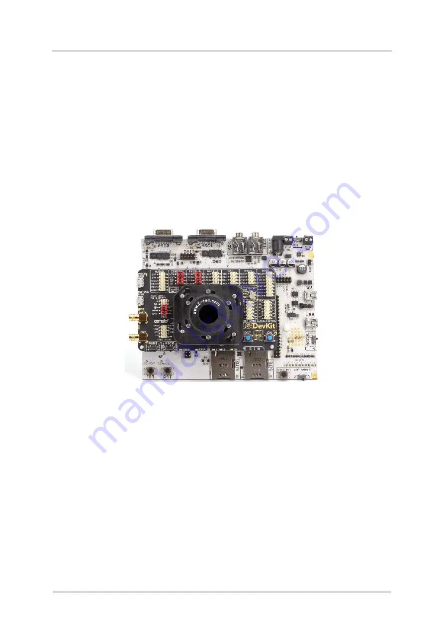
Figure 12:
LGA DevKit on DSB-Mini
6.1
Quick Start Operating LGA DevKit and DSB75
To operate the LGA DevKit with the DSB75 please complete the following steps:
•
Mount the LGA DevKit onto the DSB75.
•
Insert the module.
•
Set "PWR" and "ASC0".
•
Check if all jumpers are placed at the pin header: CONTROL, ASC0_A and PWR
•
Connect the host PC to DSB75 via Sub-D.
•
Connect power to DSB75 and if needed to the LGA DevKit.
•
Press the ON button (or the DSB75 IGT button).
Figure 13:
LGA DevKit on DSB75
TBD.