DIGITAL CLOCK MODEL CLK056
GEKCO INC.
Rev 1.0
15
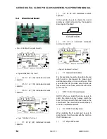
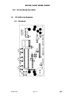
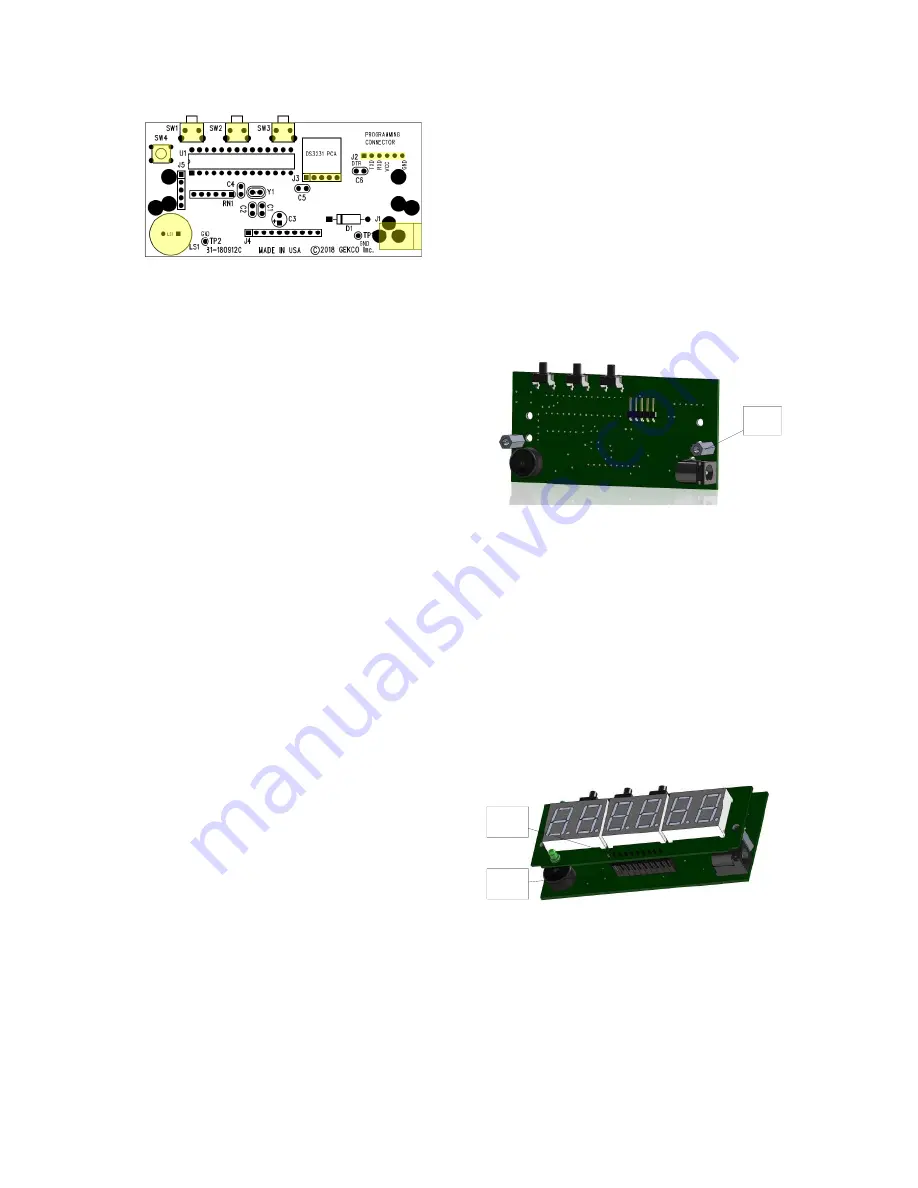
Figure 9: Main Board Top View 4
( )
SW1: momentary right angle switch
( )
SW2: momentary right angle switch
( )
SW3: momentary right angle switch
( )
SW4: momentary switch
( )
J2: Connector Header Male 6 pin right
angle mount
( )
J3: Connector Header Male 5 pin right
angle mount
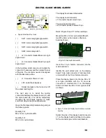
In the next step, solder one pin and re-align the
connector if necessary and then solder the rest
of the pins. The connector needs to be aligned
with the silkscreen outline.
( )
J1: Connector Power 2.1 mm
( )
LS1: Audio Piezo Speaker
( )
Solder the leads to the foil and cut off
the excess lead lengths.
The next step is to install the mating
connectors between the display board (J1) and
the main board (J4). You will be temporarily
mounting the two boards together to make
sure the mating connectors align properly.
Open the final assembly hardware bag and get
the following parts:
Quantity 2 of:
M3 x 12 mm nylon standoffs
Quantity 4 of:
M3 x 6 mm nylon screws
The display board assembled earlier.
The display board connector
J1: Connector header male 10 pin
The main board connector
J4: Connector Header Female 10 pin
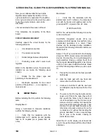
Refer to figure 10 and 11 for the next steps
Mount two M3 x 12 mm nylon standoffs with
two M3 x 6 mm nylon screws on the main
board as shown.
(2) M3x12
mm nylon
standoff
Figure 10: Main board with standoffs
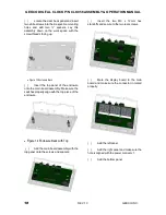
Insert the 10 pin female connector into the
main board at J4.
Identify the gold plated pins on the display
board 10 pin male connector J1 and insert into
or mate with J4 the 10 pin female connector.
Place the display board onto the two M3 x 12
mm nylon standoffs, with the 10 pin male
connector J1 inserted into J1 on the display
board and insert two M3 x 6 mm nylon screws
as shown.
DISPLAY
BOARD
J1
MAIN
BOARD
J4
Figure 11: Main and Display board Interface connector
mounting
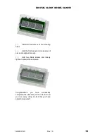
Solder the pins of the display board connector
J1 on the display board and then do the same
for the connector pins on the main board J4.

