background image


3.3


MIW3_Gb_01165_130204.doc 


4.1


Checking the fuel level

 (this check is done with the engine stopped) 

-


Check  the  fuel  level  and  top  up  if  necessary  (

:  be  sure  to  refer  to 

1.3  “General  safety  instructions”  /  “Utilisation  and  handling  of  fuel”  and  3.2.2 

“Filling with fuel”).  


Functional checks 

(these checks are done with the engine stopped) 

-


Check the correct operation of the accelerator trigger, the accelerator trigger safety lock and the combination lever. These devices must move freely and not 
be modified.  

-


Check that the shaft rotates freely under no load.  


Check of safety devices 

-


Make sure that the handles are clean and dry.  

-


Start the engine (

: be sure to refer to 

4.2 “Utilisation of the machine”) and check that the engine stops when the combination lever is moved to the “

0

” 

position.  

-


Check that the wrench does not rotate when the accelerator trigger is in the idle position (refer to §5.1.4 "Carburettor" if adjustment is required). 


Miscellaneous checks 

-


Check that no oil leaks are present and that all mounting bolts are tight.  


IF


ANY


ABNORMALITY


IS


FOUND


DURING


THIS


INSPECTION


PHASE


OR


IN


THE


COURSE


OF


UTILISATION,


THE


MACHINE


MUST


BE


RESTORED


TO


COMPLIANCE


BY


COMPETENT


PERSONNEL


OR


BY


THE


MANUFACTURER


BEFORE


BEING


USED


AGAIN


CHAPTER 4 – UTILISATION 
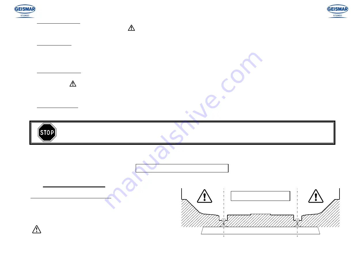
 

4.1


Conditions of utilisation  

Working zone and position of operator 

The operator must work in the zone between the two rails of the same 
track. The operator must be inside this zone in order to carry out bolting 
or screwing work (on the inside and outside of the rail).  

If  specific  work  has  to  be  done  from  outside  the  working  zone, 
check the safety conditions, particularly if traffic on the adjacent 
line is not interrupted.  

WORKING ZONE 

Summary of Contents for MIW.3

Page 1: ... MIW 3 PORTABLE MOTOR IMPACT WRENCH MIW 3 ANGLAIS ...

Page 2: ... ...

Page 3: ...f the world of railways This machine built entirely in France from design through to delivery has been subjected to continuous extremely strict controls Formed of different mechanical elements assembled by highly qualified fitters your machine has been tested calibrated and controlled at every stage of its production We are convinced that it will give you every satisfaction and are of course at yo...

Page 4: ... Utilisation of the machine 4 3 Storage 4 3 1 General instructions for storage 4 3 2 Particular instructions for storage CHAPTER 5 SERVICING AND MAINTENANCE 5 1 Servicing 5 1 1 List of equipment and accessories necessary for servicing 5 1 2 Cleaning 5 1 3 Tightening 5 1 4 Carburettor 5 1 5 Spark arrester grille on silencer 5 1 6 Spark plug 5 1 7 Reducer and shock absorber 5 1 8 Removing the shock ...

Page 5: ...arefully with the general safety instructions drawn up for the site by the person in charge of the site especially if the work is carried out without stopping or diverting traffic The equipment can only be used serviced or repaired by competent personnel who have undergone thorough specialized training beforehand The technical documentation and the instructions are useful in completing the knowled...

Page 6: ...areas must be free of all flammable substances If anything does not seem clear to you whether it concerns the machine or the work to be carried out ask a qualified person for information Do not base your work on assumptions For underground use tunnel or gallery or in a closed area make sure there is sufficient ventilation or extraction to avoid the risks generated by inhaling exhaust gases or by t...

Page 7: ...carried out by suitably qualified persons Read and make sure you fully understand all the signs placed on the machine and always comply with all the instructions The signs placed on the machine include pictograms manufacturer s plates and instruction labels Make sure they are kept clean and replaced if they have been damaged or if they are missing or illegible If one of these elements is on a part...

Page 8: ...leased without spraying any fuel out Take special care if the surrounding temperature is high When putting fuel in a machine that has heated up never fill the tank completely Do not put in more than three quarters of the tank capacity If fuel starts to boil in the tank when putting fuel in a machine that has heated up screw the cap on again immediately and leave the machine to cool down Make sure ...

Page 9: ...he starter rope around your hand and never release it suddenly If the machine does not operate correctly after the engine has been started stop the engine and inform the head of maintenance For petrol engines use only spark plugs whose tops are as shown in drawing 1 opposite If the plug is fitted with a screw top make sure the top is fully tightened After fitting the spark plug make sure that the ...

Page 10: ...afety instructions the operator and his environment The operator must wear a helmet and safety shoes with non slip soles and steel caps It is also advisable to use a means of protection against the inhalation of exhaust fumes The use of ear protection is also recommended strictly complying however with the applicable railway regulations applicable on the site in order to determine whether or not s...

Page 11: ...t in starting the engine Do not use the choke while working it should only be used when starting It is mandatory to stop the engine before undertaking any servicing or maintenance operation If it is essential for the engine to run carburettor adjustment and verification of maximum no load speed make sure that the working zone is well ventilated Never use the portable power wrench of the exhaust si...

Page 12: ...l pump and electronically controlled magneto ignition Depending on the situation the machine can be used horizontally for fishplate bolts and nuts or vertically for lag screws The MIW 3 was developed in an exclusive partnership between GEISMAR STUMEC and STIHL and is thus the only portable power wrench to be type approved with a STIHL engine The MIW 3 is also notable for its effective protection a...

Page 13: ...haust silencer with exhaust shield F 1 25 4 mm square drive G Impact device H Rotation speed reducer J Oil drain refill plug K Oil level indicator L Front handle M Reverse lever N Accelerator trigger lock P Starter handle Q Air filter cover screw R Fuel tank cap S Universal start stop lever T Accelerator trigger F A B C D E G J H P K L R S T N Q M ...

Page 14: ...5 2 Vibrations Vibration level in operation Aeq 3 ms 2 11 7 2 Machine Set idling speed rpm 2800 Maximum tightening torque N m 2000 Maximum release torque N m 2600 Maximum rotating speed of square drive rpm 1400 Engine Type STIHL MS 311 Cubic capacity cm 59 Power 9500 rpm kW 3 1 Cylinder bore mm 47 Maximum speed rpm 13000 Piston stroke mm 34 Carburettor Membrane carburettor Operating cycle 2 stroke...

Page 15: ..._01161_130204 doc 2 4 2 4 Position of the machine relative to the track The diagram below shows the dimensions of the machine with respect to the UIC 505 1 standard nominal rail separation 1435 mm 510 305 715 105 ...

Page 16: ...hen loosen the flexible ring 解 The output shaft has a 1 25 4 mm square drive Ref 56036 Use special fittings for impact sockets size 32 to 42 with a 1 square drive and fixing by pin Ref 56043 and flexible retaining ring Ref FPR Fitting a reducer diminishes the efficiency of the machine 3 2 Fuel 3 2 1 Preparing the mixture The two stroke engine of the impact wrench must be supplied with a mixture of...

Page 17: ...ainer Finally pour in the remainder of the petrol Carefully mix again before refilling the machine Mixing ratio STIHL 2 stroke engine oil 1 50 1 part oil 50 parts of petrol other good quality 2 stroke engine oil 1 25 1 part oil 25 parts petrol Storing the mixture a mixture prepared with unleaded petrol is not stable for long periods The mixture must therefore be prepared when it is needed not in a...

Page 18: ...k cap in the open position The mark on the tank cap and the open position symbol marked on the machine must coincide Fig 4 Push the fuel tank filler cap down until it stops Maintaining the pressure on the tank cap turn it fully clockwise approximately of a turn Fig 5 If this works correctly the markings on the inner ring and outer ring of the tank filler cap should coincide Fold the handle down Th...

Page 19: ...n lever is moved to the 0 position Check that the wrench does not rotate when the accelerator trigger is in the idle position refer to 5 1 4 Carburettor if adjustment is required Miscellaneous checks Check that no oil leaks are present and that all mounting bolts are tight IF ANY ABNORMALITY IS FOUND DURING THIS INSPECTION PHASE OR IN THE COURSE OF UTILISATION THE MACHINE MUST BE RESTORED TO COMPL...

Page 20: ... place the universal control lever in the desired position To move to the starting position first bring the universal control lever to the choke closed position then push the universal control lever to the starting position Moving to the starting position is only possible from the choke closed position When the accelerator trigger lock is pressed while simultaneously pressing then releasing the ac...

Page 21: ...or trigger lock and blip the accelerator trigger the universal control lever releases and returns to the normal running position with the engine running at idle Accelerate slightly for a few moments to allow the engine to warm up If appropriate make the adjustment for winter use see winter use If the engine does not start at the first attempt the universal control lever has not been set in a timel...

Page 22: ...tal position Accelerate the engine The socket commences its releasing movement after a few seconds If the component refuses to release never pursue continuous impact operation for more than 10 seconds Reverse the direction of operation and try to release the bolt or lag screw by tightening it for 3 seconds Continue the releasing operation and if release is not obtained after 10 seconds of impact o...

Page 23: ... receives warm air from around the cylinder which prevents the carburettor from icing For temperatures above 20 C It is essential to return the slider to the summer use position in order to avoid overheating and poor engine performance For temperatures below 10 C If the engine idling speed is uneven or if acceleration is not satisfactory turn the idling richness adjustment screw L of a turn anticl...

Page 24: ...ed around the machine for maintenance operations Storage premises As a general rule premises intended for equipment storage must provide the best possible protection against dust exhaust gases and humidity direct sunlight rapid temperature variations Placing in storage The condition of equipment when returned to service after storage depends on the manner in which the equipment was prepared prior ...

Page 25: ...mance of servicing and maintenance work the following tools must be available Servicing tools supplied with the machine Servicing and maintenance tools not supplied with the machine Flat screwdriver Ref 0000 890 2300 Plug spanner Ref 1129 890 3401 Multigrip pliers Spanner 8 mm Flat spanner 13 x 23 GAW 1 Ring FPR and 1 Pin 56043 Tool kit Ref 0000 891 0810 Allen keys 3 4 5 and 6 mm Torx key 27 mm Th...

Page 26: ...tment screws only very slightly and with great care since the smallest rotation results in a significant change in the engine running speed Adjustment of the screws on this carburettor are only possible within narrow limits If the mixture setting is too weak this may result in a lack of lubrication and consequent overheating Standard adjustment Stop the engine Inspect the air filter replace it if ...

Page 27: ...he engine does not run satisfactorily H Turn the high speed mixture screw clockwise to weaken the mixture to the limit against the stop 5 1 5 Silencer spark guard For certain countries the silencer is fitted with a spark guard If the engine power diminishes check the spark guard Before undertaking this operation wait until the engine has cooled down completely Undo the screw Take out the spark gua...

Page 28: ...lug if the plug is fouled clean it with a fine wire brush Then check that the electrode gap is set to 0 5 mm Correct the gap if necessary if the electrodes are heavily worn replace the plug Always use interference suppressed plugs see 2 4 Technical characteristics Other plug types may damage the piston cylinder After cleaning the plug and starting the machine eliminate the possible causes of plug ...

Page 29: ...tic oils Check the oil every day by means of the indicator 解 When the machine is vertical the oil should reach the middle of the indicator approximate capacity 0 7 litres Change the oil every 40 hours of operation approximately For a new machine change after 10 hours When draining the oil clean the magnetic plug 会 which retains metal particles present in the oil A slight presence of particles is n...

Page 30: ... Fig 1 Take out the drive nose the spring and the ring Fig 2 Place the mechanism in a soft jawed to avoid damage vice then tighten the hammer and the satellite carrier Fig 3 until the 2 ball bearings can come out of their housing Fig 4 WARNING At this point there is nothing to retain the ball bearings in the stop Release the vice The hammer can now be removed Take out the striker spring Take out t...

Page 31: ...le Remove any pieces of cable remaining in the cable pulley and in the starter handle Feed the new starter cable into the handle and make a special knot in the end Pull the knot into the starter handle From the top pass the end of the cable through the cable guide and the cable pulley and secure it with a single knot Moisten the bore of the cable pulley bearing with resin free oil Slide the cable ...

Page 32: ...ne turn of cable out of the pulley Fit the fan housing Fit the cover and tighten the screws firmly 5 1 11 Replacing the return spring Remove the cable pulley following the operations 1 to 3 described in 5 1 9 Replacing the starting cord Remove the pieces of spring carefully using a screwdriver as a lever Moisten the new spring with a few drops of non resinous oil Position the new spring with its m...

Page 33: ... clean non inflammable solution Dry the filter Do not brush the filter Fitting the air filter Engage the ribs in the grooves Swing the air filter towards the filter box and lock the clamp Refit the cover and tighten the screws firmly The separation power and permeability to air of all air filter components of the machine are correctly matched For the above reason use only original air filters see ...

Page 34: ...r from clogging protect the fuel tank from contamination when refilling 5 1 14 Cooling system The cooling system maintains the operating temperature of the portable wrench at the lowest level thus avoiding damage to the cylinder and piston To maintain the full efficiency of the system it should be cleaned once per week using compressed air Undo the four screws multiple key Remove the fan cover Cle...

Page 35: ...lean cloth or a blower to remove deposits of dirt from the machine X Chap 5 1 2 Control devices Check operation X Chap 3 3 Accessible screws and nuts except adjusting screws Re tighten X Chap 5 1 3 Carburettor Check that the square drive does not rotate when the engine is idling X Chap 5 1 4 Adjust X Silencer spark guard if fitted Clean X Chap 5 1 5 Replace X Spark plug Check electrode gap X Chap ...

Page 36: ...PERATION FREQUENCY Reference Before each utilisation After each utilisation Weekly Monthly Annually In the event of failure In the event of damage As required Impact system Check oil level X Chap 5 1 7 Change oil X Starting cable Replace X Chap 5 1 9 Return spring Replace X Chap 5 1 11 Damping washer Replace X X X Chap 5 1 8 Filtration system Clean filter box and surrounding area X Chap 5 1 12 Rep...

Page 37: ...FPE 1 Oil leak or poor performance Seal BA 34 x 46 x 8 FPF 1 Shim washer 56028 1 Seal Ø 17 x 28 x 7 FBE 1 Spark guard 1140 140 8100 1 Clogging Suction strainer 0000 350 3504 1 Air filter 1140 121 6900 1 Spark plug Bosch WSR 6 F 1110 400 7005 1 Plug electrodes heavily worn Spark plug NGK BPMR7A 0000 400 7000 1 Lower protection 56159 1 Damage Prefilter 1140 140 4401 1 Starting cable Ø 3 5 x 960 mm 1...

Page 38: ...gned to facilitate the use of the power wrench for work on sleeper fishplates 6 1 3 Accessories Sockets with different square sizes can be used by fitting a reducer Ref 56076 between the output shaft and the tightening socket Then use the ball bearing mounting system Ref 880 E Ball bearing mounting system Ref 880 E comprising Ball cage Ref 17916 Spacer Ref 17913 Sleeve Ref 881 A Spring Ref 882 Ste...

Page 39: ...1 4 N05415 Hex MIW socket 41 N04478 Octagonal MIW socket 60 32 2 3 8 N05458 Hex MIW socket 42 N03487 Octagonal MIW socket 63 50 2 1 2 N05459 Hex MIW socket 43 N03482 Square MIW socket 17 N04985 Hex MIW socket 44 N05430 Square MIW socket 19 N03829 Hex MIW socket 45 N04871 Square MIW socket 20 N03472 Hex MIW socket 46 N05427 Square MIW socket 20 64 13 16 N05636 Hex MIW socket 53 97 2 1 8 N05655 Squa...

Page 40: ... square socket 41 27 1 5 8 N04715 MIW square socket 42 N04869 MIW socket Torx adapter 70 N05433 MIW rectangular socket 19x26 N04628 MIW rectangular socket 21x28 N02776 MIW rectangular socket 21x28 SL N05830 1 1 socket extender Length 125mm N05435 1 1 socket extender Length 175mm N05721 1 1 socket extender Length 200mm N02819 1 1 socket extender Length 330mm N02823 ...

Page 41: ...ith 25 4 23 mm reducer adapter ref 56000 D Designation Reference Hex screwing socket 19 05 3 4 Length 80mm N00033 Hex screwing socket 24 Length 80mm N00013 Hex screwing socket 27 Length 80mm N01992 Hex screwing socket 43 Length 80mm N02816 Hex screwing socket 46 Length 80mm N00025 Hex screwing socket 47 Length 80mm N02356 Octagonal screwing socket 50 Length 80mm N02727 Octagonal screwing socket 23...

Page 42: ...t 38 SL long series Length 130mm N03836 Hex screwing socket 39 Length 80mm N00099 Hex screwing socket 39 SL long series Length 170mm N04202 Hex screwing socket 40 Length 80mm N00100 Hex screwing socket 41 Length 80mm N00101 Hex screwing socket 42 Length 80mm N00102 Hex screwing socket 44 Length 80mm N00103 Hex screwing socket 50 Length 80mm N03799 Octagonal screwing socket 22 22 7 8 Length 80mm N0...

Page 43: ... SL long series Length 100mm N03921 Square screwing socket 23 TYPE SNCF Length 135mm N02806 Square screwing socket 24 Length 80mm N03871 Square screwing socket 25 Length 80mm N04702 Square screwing socket 27 Length 80mm N00088 Square screwing socket 27 SL long series Length 140mm N04717 Square screwing socket 28 Length 80mm N05749 Square screwing socket 32 Length 80mm N04555 Rectangular screwing s...

Page 44: ...7 1 CH7_Gb_01046_120423 doc 7 1 CHAPTER 7 SPARE PARTS CATALOG 7 1 Drawings and parts lists Key to symbols Including Ind N D Not available as separate item Previous models Set of gaskets ...

Page 45: ... To ensure that you are delivered promptly and correctly after placing an order for spare parts please state the Reference number and description of the spare parts the type and serial number of the machine to locate this number look at the plate on the chassis WICHTIG Um uns eine schnelle und fehlerlose Erledigung lhres Ersatzteil Auftrages zu erlauben bitten wir Sie um folgende Angaben Seriennum...

Page 46: ......

Page 47: ......

Page 48: ......

Page 49: ......

Page 50: ......

Page 51: ......

Page 52: ......

Page 53: ......

Page 54: ......

Page 55: ......

Page 56: ......

Page 57: ......

Page 58: ......

Page 59: ......

Page 60: ......

Page 61: ......

Page 62: ......

Page 63: ......

Page 64: ......

Page 65: ......

Page 66: ......

Page 67: ......

Page 68: ......

Page 69: ......

Page 70: ......

Page 71: ......

Reviews: