CONTROLS
62
Accessories
Auxiliary Hydraulic Lines
WARNING
�
Oil may spray out if caps or filters are
removed or pipes disconnected before
releasing the pressure in the hydraulic
system.
• When
removing
plugs
or
disconnecting hoses, release the
internal pressure before removing.
�
Hydraulic fluid, tubes, fittings and quick
couplers can get hot when running
machine and attachments.
Be careful when connecting and
disconnecting quick couplers.
These lines deliver the hydraulic oil necessary
for operating other attachments.
�
Auxiliary hydraulic flow rate and rated
pressure:
Flow Rate ...............
CTL55: 57 L/min (15.1 US gpm)
CTL65: 70 L/min (18.4 US gpm)
CTL75: 75 L/min (19.8 US gpm)
CTL85: 89 L/min (23.4 US gpm)
Rated Pressure ........ 20.6 MPa (2987 psi)
Quick-Couplers
Connecting: Remove dirt or debris from
the surface of both the male and female
couplers, and from the outside diameter of
the male coupler. Visually check the couplers
for corrosion, cracks, damage or excessive
wear. If any of these conditions exist, the
coupler(s) must be replaced.
Install the male coupler into the female
coupler. Full connection is made when the
ball-release sleeve slides forward on the
female coupler.
Disconnecting: Hold the male coupler.
Retract the sleeve on the female coupler
until the couplers disconnect.
Releasing Residual Pressure
Connecting: Push the quick-couplers tightly
together and hold for five seconds; the
pressure is automatically released as the
couplers are installed.
Disconnecting: Push the quick-couplers
tightly together and hold for five seconds;
then retract the sleeve until the couplers
disconnect.
Connecting the Hydraulic Circuits
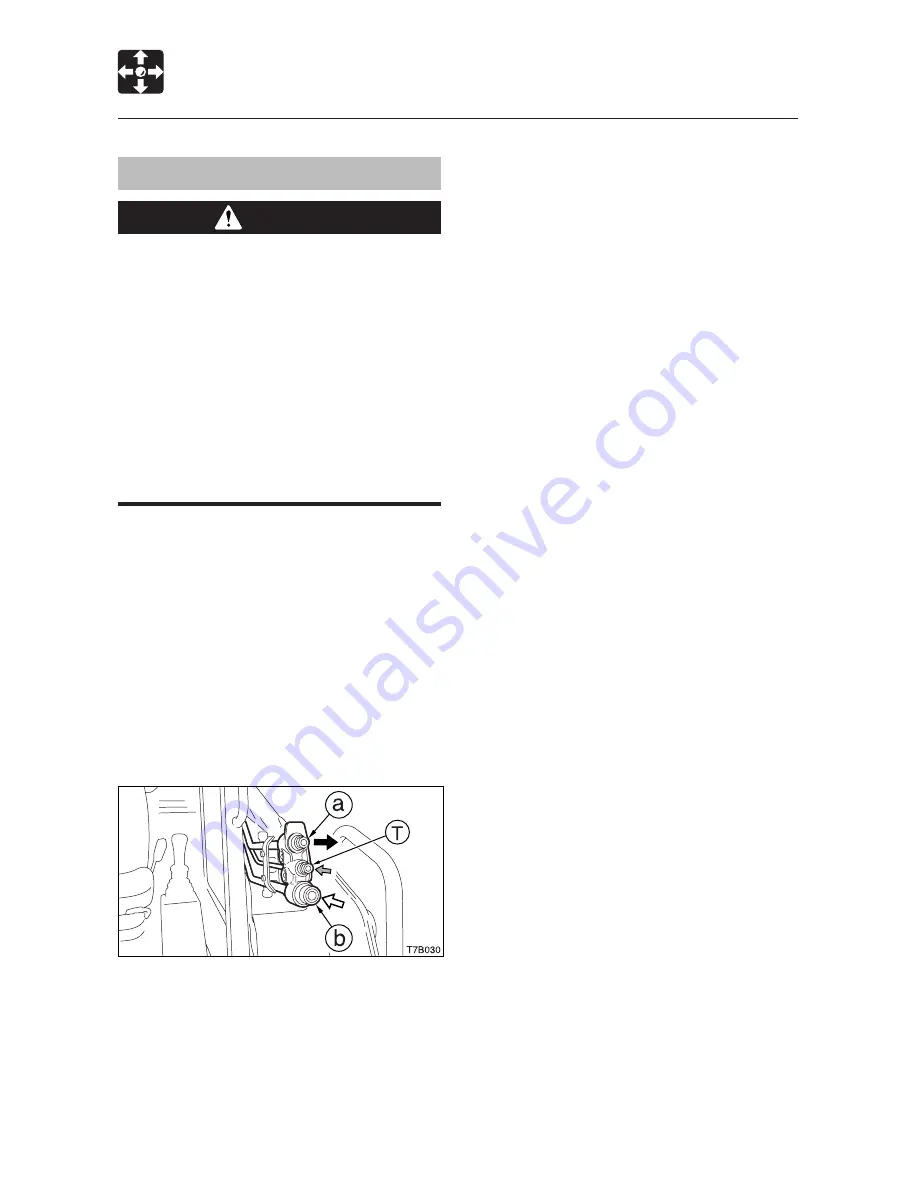
To connect attachment hydraulic lines, use
the following procedures:
1. Connect the attachment hydraulic lines to
ports (a) and (b).
When fitted with a hydraulic breaker:
a. Connect the return circuit to port (b)
and the supply circuit to port (a).
b. Turn on the flow selector switch.
Refer to page 56 “Flow Selector
Switch.”
Some attachments may have a case
drain, which needs to be the connected
to the small port (T).
2. When connecting is complete, purge air
from the hydraulic lines.
a. Start and run the engine at low idle with
no load for 10 minutes.
b. With the engine running at low idle,
operate the auxiliary hydraulics switch
repeatedly (approx. 10 times) to purge
air from the hydraulic lines.
c. Stop the engine and wait for more than
5 minutes until bubbles escape from
the hydraulic oil in the tank.
Summary of Contents for CTL55
Page 1: ...CTL55 CTL65 CTL75 CTL85 Compact Track Loader OPERATOR S MANUAL Revision E 09 10...
Page 6: ...4...
Page 8: ...6...
Page 38: ...SAFETY 36 Safety Signs Decals...
Page 39: ...37 SAFETY Safety Signs Decals...
Page 40: ...SAFETY 38 Safety Signs Decals...
Page 66: ...64 MEMO...
Page 67: ...65 MEMO...
Page 68: ...66 MEMO...
Page 69: ...67 MEMO...
Page 70: ...68...
Page 114: ...MAINTENANCE 112 Maintenance Log Date Hours Service Procedure...
Page 115: ...113 MAINTENANCE Maintenance Log Date Hours Service Procedure...
Page 123: ...121 MEMO...
Page 129: ...127 MEMO...
Page 156: ...154...
Page 170: ...168...
Page 171: ...169 Main Speci cations 170 Machine Dimensions 174 Operating Range 176 SPECIFICATIONS...
Page 176: ...SPECIFICATIONS 174 Machine Dimensions...
Page 178: ...SPECIFICATIONS 176 Operating Range T7K0021 F H C A D B G E...
Page 180: ...178...
Page 181: ...179 General Precautions 180 Air Conditioner CTL55 182 OPTIONS...
Page 193: ...191 MEMO...
Page 194: ...192...
Page 195: ...193 INDEX...


