background image

10

80636B_MAN_HMF - HWF_05-2022_ENG

5� Mechanical Dimensions

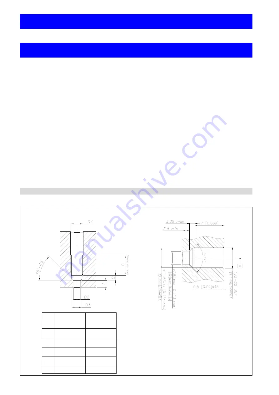
The installation seat has to be realized:

  D1 

1/2-20UNF M18x1�5

  D2 

.313 ±.001” 

.398 ±.001”


[7.95 ±0.02mm] 

[10.10 ±0.02mm]

  D3 

.454 ±.004” 

.634 ±.004”


[11.53 ±0.1mm] 

[16.10 ±0.1mm]

  D4 .515” 

[13mm]

 .790” 

[20mm]


minimum 

minimum

  A .225” 

[5.72mm]

 .240” 

[6.10mm]


minimum 

minimum

  B .17” 

[4.3mm]

 .16” 

[4.0mm]


maximum 

maximum

  C .75” 

[19mm]

 .99” 

[25mm]

Rigid rod / flexible sheathing / flexible plus thermocouple version

Exposed capillary version

6� Installation and positioning on the machine

TECHNICAL DATA
Extrusion processes require very high temperatures. Extrusion pressure can be checked by means of especially 

designed transducers. Thanks to their special mechanical construction, in which the measurement element is 

isolated from the Melt, they resist to such high temperatures. The constructive principle is based on hydraulic of 

pressure; mechanical strain is transferred by means of a non-compressible transmission liquid.

Strain gauge technology translates the physical quantity (pressure) into an electrical signal.

Following advice for extending the sensors lifetime.

a) Avoid shocks and abrasions to the in contact diaphragm. Protect the transducer with its cover each  

    time you remove it from its seat.

b) The seat must be prepared perfectly and with appropriate tools in order to respect the depth and axiality  

    of the holes and tapping.

Pay particular attention to the coaxiality of the holes to the thread, because diaxialities greater than 0.2 mm will 

break the transducer during assembly. It is essential that hole depth guarantees the absence of chambers or air 

pockets in which extrusion material may be trapped.

To prevent contact with the extrusion screw or with tools used to clean the extrusion chamber, the front diaphragm 

must not extend from the inner wall of the extruder.

c) Before assembling the transducer in machines already in operation, make sure that the housing is clean.

    Remove any residual with the suitable cleaning device.

d) The transducer should be removed only with the machine empty (without pressure) but still hot.

e) The transducer should be cleaned with solvents for the material being processed.

Any mechanical action on the contact diaphragm modifies its operation and could break it.

6�1�  Installation seat

For the mechanical dimensions please keep as reference the product datasheets or Gefran website www.gefran.com

Summary of Contents for HMF P

Page 1: ... this manual and scrupulously follow all of the instructions in it and in its attachments GEFRAN will not be liable for damage to persons and or property or to the product itself if the following terms and conditions are disregarded The customer must respect trade secrets Therefore this manual and its attachments may not be tampered with changed reproduced or trans ferred to third parties without ...

Page 2: ...2 80636B_MAN_HMF HWF_05 2022_ENG ...

Page 3: ...nd positioning on the machine 10 6 1 Installation seat 10 6 2 Drilling tool kit 11 6 3 Wiring and calibration 13 7 Electrical Connections 14 8 Command modes 15 8 1 Using Magnetic pen and Pin CAL 15 8 2 Using HART communication 17 9 Maintenance 23 9 1 Transport storage and disposal 23 10 Functional Safety notes for SIL 2 PL d certified versions only 24 10 1 NE21 and NE43 compatibility specification...

Page 4: ...rature itself is stable with a pos sible variation of 1 C Consequently Autozero can be activated This allows to compensate all the signal drifts caused by tightening and temperature Additional Autozero activations could be run once the temperature stability is reached with 1 C of possible variation 2 Calibrate the instrument activating the CAL function The transducer brings its output to the calib...

Page 5: ...5 TV Snout Temp 6 Sensor Information 1 PV Pressure 2 PV range 3 PV Loop Cur 4 SV Elect temp 5 TV Snout Temp 6 Sensor Information 1 Alarms Warnings 2 Peak Temperature 3 Peak Pressure 4 Peak Snout Temp 1 Re range 2 D A Trim 3 Sensor trim 4 Device variable trim reset 5 Rcal psi bar kg Sqcm MPa KPa 1 Date 2 Descriptor 3 Message 1 Process variables 2 Re range 3 Pressure Unit 4 PV Min Span 5 PV Damp 1 P...

Page 6: ...filling fluid used The correct temperature range is Up to 315 C for HW series i e oil filling fluid Up to 400 C for HM series i e mercury filling fluid If the sensors are used as a safety component in compliance with the Machinery Directive it s necessary to read carefully the Safety Manual chapter 10 In case the sensors are used for applications in potentially explosive atmospheres please read ca...

Page 7: ... these sensors may be mercury i e HM series or FDA approved oil i e HW series Strain gauge technology translates the physical quantity pressure into an electrical signal Five different designs are available rigid rod flexible sheathing flexible plus thermocouple exposed tip and flange mount Gefran Melt sensors satisfy all installation and field requirements The sensors can read an extremely wide r...

Page 8: ...ting temperature range housing 30 85 C Storage temperature range housing 40 125 C Thermal drift in compesated range Zero Calibration Sensibility 0 02 FS C Diaphragm maximum temperature 315 C 600 F Zero drift due to change in process temperature zero 0 04 bar C Standard material in contact with process medium Diaphragm 17 7 PH corrugated diaphragm with GTP coating Stem 17 4 PH Protection degree IP6...

Page 9: ...emperature 400 C 750 F Zero drift due to change in process temperature zero 0 02 bar C Standard material in contact with process medium Diaphragm 15 5 PH with GTP coating 17 7 PH corrugated diaphragm with GTP coating for ranges 100 bar 1500psi Stem 17 4 PH Protection degree IP67 NEMA 4X Electomagnetic compatibility Emissions EN 61326 1 EN 61326 2 3 EN 61326 3 1 Electomagnetic compatibility Immunit...

Page 10: ...d shocks and abrasions to the in contact diaphragm Protect the transducer with its cover each time you remove it from its seat b The seat must be prepared perfectly and with appropriate tools in order to respect the depth and axiality of the holes and tapping Pay particular attention to the coaxiality of the holes to the thread because diaxialities greater than 0 2 mm will break the transducer dur...

Page 11: ...l to the sum of A B tool 6 6 To ream the hole D2 with reamer tool 2 Installation seat check The dimensions of the assembly seat have to be checked after preparation and before the transducer installation Use dummy plug SC 12 18 as follows 1 Coat the end of the rod with the appropriate ink 2 Lubricate the threaded part to prevent friction 3 Insert the dummy plug and screw it fully down 4 Remove the...

Page 12: ...be vibration free vibrations affect the measurement and that tem peratures must not exceed the maximum temperature range for the strain gauge housing as stated on the sensor technical sheet Extruder starting Bring the system to working temperature with the transducer installed and without any pressure applied Wait until all the material is at the same temperature to prevent the transducer damage b...

Page 13: ...ansducer brings its output to the calibration value shown on the transducer data plate 80 of full scale default if changed with HART command it could be different With the external Autozero function the calibration procedure is not feasible 3 If the instrument does not exactly indicate zero repeat points 1 and 2 In this way the instrument is calibrated to give the exact indication in the chosen en...

Page 14: ...ig 7 1 where are also pointed out the connections 2 wires connection current amplified In the case of relay output with retransmitted output in current 2 wires the connections are shown in Fig 7 2 CURRENT OUTPUT NO RELAY The cable shield is tied to both sides i e to the sensor connector and to the controller Fig 7 1 Fig 7 2 Cable outlet 1 2 14 NPT L 1 m Current output ...

Page 15: ...move Magnetic pen 2 5 seconds marked spot Application mode Limits Result FS bar adjustment The Autozero function is activated by 1 positioning the magnet near the Autozero label on the shell of the sensor 2 Short circuiting the pin E F external Autozero version The magnet has to be maintained on the Autozero position for a time within 2 to 5 seconds 35 100 The Autozero effect will be visible after...

Page 16: ... to the 80 FS The calibration effect is visible 2 secon ds after short circuiting E F The Calibration function doesn t work outside the defined limits NOTE The Calibration function is not allowed for external Autozero version 3 Total reset of the calibration values Application mode Limits Result The magnet has to be maintained on the Autozero position for a time of 20 to 25 seconds The Zero and Sp...

Page 17: ...ator LCD display should show H Pressure Transmitter in the upper left corner If this is not present please refer to chapter 9 Safety Troubleshooting section 4 Set PV Units Fast Key 1 3 3 to proper pressure unit e g bar psi kgf cm MPa etc 5 Set Tag Fast Key 1 3 1 6 In case the transmitter output has to be re ranged fix the proper LRV Fast Key 7 1 and URV Fast Key 8 1 Note URV can t be turned down b...

Page 18: ... can be regulated using the Device Variable Trim method fast key 1 2 6 3 3 Please apply Zero Pressure firstly and follow the prompts on the handheld HART Communicator Once completed please apply a known calibrated full scale pressure to the transmitter and follow the prompts on the handheld HART Communicator Once completed the digital PV will be corrected to full scale output Transmitter functions...

Page 19: ... calibrated pressure source only URV Rerange by applying a known pressure 1 2 6 1 2 Such a function is performed by applying a known pressure and starting the procedure in order to set the 20mA point according to the pressure reference value Note Such an operation should be carried out with a calibrated pressure source only Device Variable Trim reset 1 2 6 4 This function is used to restore the Ze...

Page 20: ... 0 Input stage error 1 Sensor overrange 2 Sensor broken 3 Micro controller overheated 4 Error parameter 5 Voltage error 6 Watchdog error Bit Function 7 Cycle error Sensor Status 2 Bit Function 0 Reserved 1 Sensor under range 2 Low loop voltage 3 Not used 4 Not used 5 Not used 6 Not used 7 Not used PV Unit 1 3 3 The PV unit sets the unit of measure that the pressure related parameters are transmitt...

Page 21: ... is in Multidrop mode For instance a Multidrop mode would be a group of Hart devices wired in parallel on a single fed loop and each device being assigned a unique poll address 1 15 The Hart communicator would prompt for the single transmitter address to communicate with and would poll that particular device only All others would remain unvaried Burst configuration 1 4 2 3 4 If the transmitter is ...

Page 22: ...orm D A Trim 1 2 6 2 Perform Autozero 1 2 6 3 1 Reset Autozero 1 2 6 3 2 Perform Device variable trim 1 2 6 3 3 Device variable trim reset 1 2 6 4 Set Rcal 1 2 6 5 Set Tag 1 3 1 Set Long Tag 1 3 2 Set PV Unit 1 3 3 Set Lower Range Value LRV 1 3 4 5 Set Upper Range Value URV 1 3 4 4 Display Lower Set Limit LSL 1 3 4 1 Display Upper Set Limit USL 1 3 4 2 Set Date 1 3 5 1 Set Descriptor 1 3 5 2 Set M...

Page 23: ...cological sheet Further HW series melt sensors are totally compatible with the European Directive RoHs on the restriction of the use of certain hazardous substances in electrical and electronic equipment 9 1 Transport storage and disposal Melt sensors are made with Filled technology and contain a pressure transmission fluid Low compression fluids such as diathermic oil FDA and USDA approved or mer...

Page 24: ...he SIL PL parameters of the transducer are shown in the table below Parameter Value Measuring Unit Architecture 1oo1 D HFT 0 Category 2 β βD factors 0 02 λDD Analog output 7 50E 07 1 h λDU Analog output 1 13E 07 1 h DCavg Analog output 90 SFF Analog output 92 68 MTTFd Analog output 132 years PFH Analog output 1 13E 07 1 h Systematic capability 2 SILCL IEC EN 62061 SIL IEC EN 61508 2 PL EN ISO 1384...

Page 25: ...ges accordingly considering a Damping filter value other than 0 summing the value of Damping filter to 250ms The response time in case of a detected fault is Analog out 500 ms The response time in case of a detected fault is not affected by Damping filter value Suspension of the safety function In H series transducer it s not allowed any suspension or bypass of the safety function Indications and ...

Page 26: ...tion values burst mode No special requirements are defined for the burst mode Alarm and Saturation values in multidrop mode If the device is in multidrop mode the NAMUR levels are no longer achievable Instead the fail safe condition is indicated by the field device status and by the additional diagnostics Mainteinance and troubleshooting To maintain the device in the designated category it must be...

Page 27: ...he electrical continuity between the female plug and the power supply 4 Check if the power supply level is within specifications 5 Check voltage supply stability 6 Check possible housing overtemperatures Remove the reasons wait till cooling down and switch on the sensor 7 If the problem persists send the sensor to factory for repair 8 If the sensor works fine mount the sensor in the seat following...

Page 28: ...ully compatible with the NE21 and NE43 Namur recommendations refer to Tab 10 4 Failure HMF HMF P S HWF HWF P S Broken power cable Electrical output 3 6 mA Sensor not connected Electrical output 3 6 mA Broken power supply Electrical output 3 6 mA Broken chip Electrical output 21 mA Pin detachment Electrical output 21 mA Pressure over 200 of the span vs factory zero RT Electrical output 21 mA Preloa...

Page 29: ...ion Proof installation guidelines before inserting an HART communicator in the loop in an hazardous area The HMF and HWF series Melt pressure transmitter must be installed and serviced in conformity to plant engi neering and maintenance standards for environments classified at risk of explosion due to the presence of gas dust and fibers The HMF and HWF series Melt pressure transmitter must be powe...

Page 30: ...ressure transmitters must be installed according to the instructions in Fig 11 1 300 mm 240 mm 100 900 625 665 125 165 HMF0 HMF1 HMF3 HMF4 Contact diaphragm Es Ø8 Process connection thread Es 1 2 20UNF Process connection thread Es 1 2 20UNF Process connection thread Es 1 2 20UNF pressure transmitter housing block fluid at process temperature 315 C for HMF 400 C for HWF thermically isolating materi...

Page 31: ...TOR If the victim has fainted try to keep him in a stable position on his side as you move him Contact with skin Wash immediately with soap and water rinse thoroughly Contact with eyes Wash will running water for several minutes keeping the eyelids wide open CALL A DOCTOR Ingestion Call a doctor if victim feels ill 5 Fire prevention measures Approved fire extinguishers CO2 powder or nebulized wate...

Page 32: ...place Keep away from food drink and forage Immediately remove contaminated clothing Wash hands before taking a break and at end of shift Store protective gear separately Protective mask Use the mask in case of brief slight exposure for heavier and longerexposure wear a self contained breathing apparatus Use all service mask only in case of formation of aerosol or mist Protective gloves Neoprene gl...

Page 33: ... or sewers even in small doses Hazard for drinking water even in case of minimum leaks of pro duct in subsoil Toxic for fish and plankton 13 Information on disposal Product Recommendations Do not dispose of the product together with domestic waste Do not put in sewers Recycle if possible otherwise contact a company authorized to dispose of industrial waste Soiled packing Recommendations Dispose of...

Page 34: ...ns data sheet on safety National regulations Classification according to VbF Not applicable National regulations Class of hazardousness for waters Hazard for class 3 waters WGK3 Classif on lists very hazardous Additional regulations limitations and prohibitive decrees Maximum concentration in waste water DPR 319 76 Merli Law 0 005 mg l 16 Other information The above data are based on our current k...

Page 35: ...GEFRAN spa via Sebina 74 25050 Provaglio d Iseo BS ITALIA Tel 39 0309888 1 Fax 39 0309839063 www gefran com www gefranonline com ...

Reviews: