background image

9

IR CHANNEL CONFIGURATION

LED Indicators

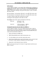
The 2x4 Switcher for HDMI 1.3 uses inactive LED and blinking LED combinations to 
indicate to the user which channel is currently active. The 

Currently Selected Input 

LED Indicators

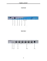
 (Item 6 on page 4 and 5) are the two LEDs used to indicate the IR 

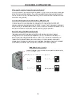
channel. These LED’s will directly correspond to DIP switches 1 and 2 on the RMT-
2IR remote control. 

LED Input Indicator 1 corresponds to DIP switch 1 on the RMT-2IR remote control.

LED Input Indicator 2 corresponds to DIP switch 2 on the RMT-2IR remote control.

An inactive LED will correspond to a DIP switch set to OFF. 

A blinking LED will correspond to a DIP switch set to ON. 

For example: 

IR Channel 2 would be indicated by the following:


RMT-2IR: 

DIP switch 1 - ON


DIP Switch 2 - OFF


Main Unit: 

LED Input Indicator 1 - Blinking


LED Input Indicator 2 - Off

Changing IR Channels on the 2x4 Switcher for HDMI 1.3.

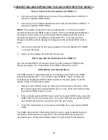
The 2x4 Switcher for HDMI 1.3 will use the EDID and Reset buttons, located on 
the rear panel, for IR channel confi guration. Use the steps below to change the IR 
channel. Please ensure that the IR channel matches on both the RMT-2IR remote 
control and the 2x4 Switcher for HDMI 1.3.

1. 

Press and hold down the EDID button.

2. 

While holding the EDID button, press the Reset button once.

3. 

The LED indicators for the current IR channel will be active.

4. 

While holding the EDID button, press the Reset button once to cycle to the next 
IR channel. The LED indicators will indicate the IR channel change.

5. 

Repeat step 4 until the desired channel is reached.

Note: 

The IR channel will cycle from Channel 1 through Channel 4 and then cycle 

back to  Channel 1. 

Summary of Contents for EXT-HDMI1.3-244

Page 1: ...www gefen com f 2X4 Switcher for 1 3 EXT HDMI1 3 244 User Manual ...

Page 2: ...rdhoff St Chatsworth CA 91311 www gefen com support gefen com Notice Gefen Inc reserves the right to make changes in the hardware packaging and any accompanying documentation without prior written notice 2x4 Switcher for HDMI 1 3 is a trademark of Gefen Inc 2008 Gefen Inc All Rights Reserved All trademarks are the property of their respective companies ASKING FOR ASSISTANCE Rev XA ...

Page 3: ...tion 2 Operation Notes 3 Features 4 Panel Layout 5 Panel Descriptions 6 Connecting And Operating The 2X4 Switcher For HDMI 1 3 7 RMT2 IR Remote Control Description 8 IR Channel Configuration 10 Specifications 11 Warranty ...

Page 4: ...uts accommodate the simultaneous connection of up to two high definition video sources such as satellite systems and HD DVD players Four outputs send the high definition audio video signals to up to four high definition displays Switching is done via the IR remote that is provided with the unit How It Works You simply connect all your sources to the Switcher s inputs Then connect up to four displa...

Page 5: ...MI1 3 will be enabled The 2x4 Switcher for HDMI 1 3 features an EDID selection that will allow the user to choose an external EDID from an attached display or an built in internal EDID Please see page 6 for more details The source device will output a single video resolution that all displays must be capable of accepting This devices is HDMI 1 3 compliant Please see page 3 for supported HDMI 1 3 f...

Page 6: ...o 1920 x 1200 are easily achieved Discrete IR remote included HDMI and HDCP compliant HDMI 1 3 Features Lip Sync Pass Through 225 MHz up to 12 bit YUV 444 supported 1080p Deep Color Supported XV Color Supported Color Space Conversion Supported Dolby TrueHD DTS Master Supported CEC Pass Through Package Includes 1 2x4 Switcher for HDMI 1 3 1 RMT 2IR Remote Control 2 6 Foot HDMI cables 1 5V DC Power ...

Page 7: ...4 Front Panel Back Panel 1 2 3 4 5 6 7 8 11 9 10 PANEL LAYOUT ...

Page 8: ...D for each of the four input ports The LED for the currently selected HDMI input will be active 7 EDID Selection Toggle Button This button will toggle between the internal external EDID modes To determine which mode is currently being used please note which EDID mode LED is active on the front panel of the unit 8 Reset Button This button will reset the unit and force all devices in the chain to re...

Page 9: ...Please see page 7 for a description of the RMT2 IR remote control EDID Modes and Reset Buttons The EDID source is selectable between the display connected to the HDMI output port labeled OUT 1 or the built in internal EDID These 2 modes are selectable by toggling the EDID button located on the back panel To switch modes follow the instructions below 1 Note the current EDID mode by viewing the fron...

Page 10: ...e 2x4 Switcher for HDMI 1 3 Only one input can be selected at a time and this input is then mirrored to the four HDMI outputs on the rear panel Switching Press the 1 button to switch to HDMI input 1 Press the 2 button to switch to HDMI input 2 RMT2 IR REMOTE CONTROL DESCRIPTION ...

Page 11: ... 3 but the channel selection must match on both units for proper operation How Do I change the Remote Channel There are service DIP switches on the RMT 2IR remote control for channel configuration The 2x4 Switcher for HDMI 1 3 uses a combination of buttons on the rear panel to configure the IR channel There are 4 channels available for use Please use the diagram below and information on the next p...

Page 12: ...the following RMT 2IR DIP switch 1 ON DIP Switch 2 OFF Main Unit LED Input Indicator 1 Blinking LED Input Indicator 2 Off Changing IR Channels on the 2x4 Switcher for HDMI 1 3 The 2x4 Switcher for HDMI 1 3 will use the EDID and Reset buttons located on the rear panel for IR channel configuration Use the steps below to change the IR channel Please ensure that the IR channel matches on both the RMT ...

Page 13: ... 2 Volts p p Input DDC Signal 5 Volts p p TTL Single Link Range 1080p 60 12 bit color depth 1920x1200 HDMI Connector Type A 19 Pin Female Power Supply 5V DC Power Consumption 10 Watts max Dimensions 12 W x 1 25 H x 4 25 D Shipping Weight 6 lbs SPECIFICATIONS ...

Reviews: