8
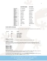
LOGIC CONNECTOR ASSIGNMENTS
Terminals 7, 8 and 9 are opto-isolator LED anode inputs in series with 200 Ohm current limit resistors. The LED cathodes go to
the COMMON terminal. The inputs work with 2.5V, 3.3V and 5V logic levels. Minimum logic 1 input current is 2 mA. Terminals 5,
6 and 7 are three opto-isolated collector outputs that have a 10 mA current sink rating and their emitters go to the COMMON
terminal.
Terminal
Function
I/O
7
RUN/STOP
INPUT
8
CW RUN
INPUT
9
CCW RUN
INPUT
10
COMMON
EXTERNAL GROUND
11
FAULT OUT
OUTPUT
12
N/C
TERMINAL 7: RUN/STOP
This input is the only way to control VCO mode on or off. Ap5VDC to TERMINAL 7 will cause the motor to accelerate to
the speed set at the CW and CCW trimpots. Re5V will cause the motor to decelerate to a stop.
TERMINAL 8: CW RUN
This input is a CW RUN input. Ap5V to this input will accelerate and run the motor to the speed set on TRIM4.
TERMINAL 9: CCW RUN
This input is a CCW RUN input. Ap5V to this input will accelerate and run the motor to the speed set on TRIM5.
TERMINAL 10: COMMON
This terminal serves as the COMMON shared GND for the RUN/STOP, CW RUN, and CCW RUN +5V inputs.
TERMINAL 11: MOTOR STOPPED
This open-collector output will go to a logic “0” when the motor is stopped. The time between signaling the motor to stop and
this output going low will be equal to the deceleration time. This output will only go low when the motor is no longer moving.
DISCLAIMER
CERTAIN APPLICATIONS USING POWER PRODUCTS MAY INVOLVE POTENTIAL RISKS OF DEATH, PERSONAL INJURY OR SEVERE
DAMAGE TO PROPERTY. GECKODRIVE INC. PRODUCTS ARE NOT DESIGNED, AUTHORIZED OR WARRANTED TO BE SUITABLE FOR
USE IN LIFE-SUPPORT DEVICES OR OTHER CRITICAL APPLICATIONS. INCLUSION OF GECKODRIVE INC. PRODUCTS IN SUCH
APPLICATIONS IS UNDERSTOOD TO BE FULLY AT THE PURCHASER’S OWN RISK
In order to minimize risks associated with the purchaser’s application, adequate design and operating safeguards must be
provided by the purchaser to minimize inherent or procedural hazards. GECKODRIVE INC. assumes no liability for applications
assistance or the purchaser’s product design. GECKODRIVE INC. does not warrant or represent that any license, either express or
implied, is granted under any patent right, copyright or other intellectual property right of GECKODRIVE INC.
MANUAL CHANGE LOG
DATE
CHANGES MADE
7/17/2018
G216 Rev-A Manual Published
2/9/2022
G216 REV1 Manual Published, with updated diagrams
5/2/2022
G216 REV2 Manual Published, pinout clarifications and standardized format


