


31
16. Appendix
16.1 Brightness adjustment
The dashboard has 8 brightness levels. To adjust the brightness, press and hold the alarm acknowledge
button and scroll through the levels by pressing the page select button. The set brightness level is
remembered for the next power-on. The brightness can only be set by use of the front panel buttons and
not from the software.
16.2 Display icons
There are three special icons (usually shown at the bottom of the display) that are used to indicate the
status of the dashboard.
Confirms that the dashboard is connected (and communicating) to a PC via the USB
connector.
Indicates that there is no CAN data being received, even though CAN channels have
been configured.
Indicates that an alarm condition is still valid even though the driver has acknowledged
the alarm. Momentarily pressing the alarm button will reveal the source of the alarm.
16.3 CAN termination
CANbus is a very robust communication network, but it must be connected and terminated correctly. Shown below is
a typical CAN network schematic:
It can be seen that each end of the bus is terminated with a 120ohm resistor. If only one resistor is fitted (or if 3 are
fitted) then the bus will probably not work at all, or at best be very unreliable.
If you’re adding the dashboard to an existing working CAN network then there is no need to add a resistor or to enable
the on-board terminator inside the dash. However, if the dash is being connected to an ECU that currently does not
connect to another CAN device then it’s important to ensure that the bus is terminated correctly at both ends.
Your ECU may or may not already have a terminator enabled. If not, start by connecting the first resistor between the
CAN-H and CAN-L pins as close to the ECU as possible. If you’re not sure if a resistor is connected internally then a
simple check is to turn off all power to the vehicle and connect a multi-meter (set to resistance) between the two CAN
wires. If a terminator is present you will measure approximately 120ohms. Incidentally, when the bus is terminated
correctly with 2 resistors you will measure approximately 60ohms when you conduct this test.
32
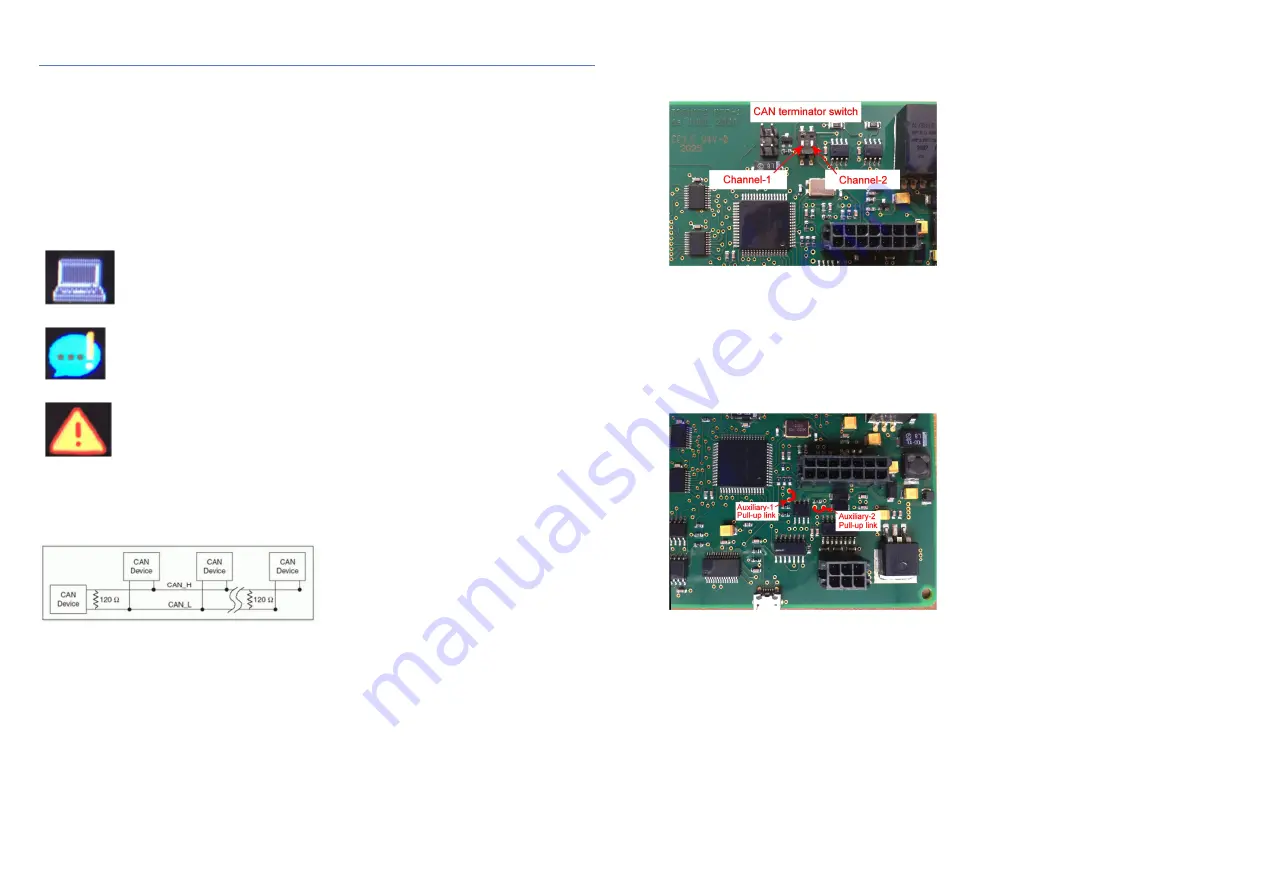
The dashboard is supplied with the CAN terminators switched OFF unless specified otherwise when ordering. If you
need to terminate the bus at the dashboard end then you can either fit an external 120ohm resistor, or you can
remove the rear panel of the dashboard and enable the internal terminator by setting the appropriate ‘DIP-switch’ to
ON. Please refer to the photograph below:
Note: the terminator switches are delicate. Use extreme caution when making changes to the switch position!
16.4 Auxiliary output pull-ups
When connecting an auxiliary output to an analogue or digital input of another device, it may be necessary to use a
pull-up resistor so that the other device can detect a voltage change when the dashboard output switches on. Many
ECUs already have pull-ups on their inputs, or there may be a function in the ECU software to enable them, but this is
not always the case. If the ECU does not have a pull-up then it will be necessary to fit an external resistor between the
ECU input and the 5v sensor supply pin. Alternatively it’s possible to enable the dashboard internal 1kohm pull-ups by
soldering a link on the circuit board. Please refer to the photograph below:
IMPORTANT: Only experienced technicians should attempt to solder the links on the PCB. Appropriate tools must be
used at all times. Warranty claims will not be entertained in the event of damage caused by incorrect soldering
techniques.
16.5 Odometer function
When used with a hall-effect wheel speed sensor to measure vehicle speed, the dashboard can calculate and display
the total distance travelled in either miles or kilometres. The odometer function does not work when vehicle speed is
derived from the CAN bus. The odometer reading cannot be reset by the user. However, a ‘trip’ function is provided
that can be reset by the user by pressing and holding the page select button for 2 seconds.
The odometer and trip counters can be found at the bottom of the channel list window. They can only be displayed as
numeric values and may only be added to the text page (page style 1).


