GEARTRONICS G-Dash Colour Dashboard Installation & Setup Download Page 11

21 


Now, select first gear and drive the car at a constant speed. We recommend using about half maximum 
engine speed when performing gear sampling. When you’re happy that the speed has stabilised, and is as 
constant as possible, press the top button to sample 1

st

 gear. After a few seconds the display will change to 

show gear 2. At this point select 2

nd

 gear and again drive the car at a constant speed before pressing the 

sample button. Continue through all the gears until top gear has been sampled. Press “Exit” (bottom button) 
to save the sampled ratios. The dash will now revert to the normal display. 

The dash should now indicate the correct gear, although it may be necessary to sample 1

st

 gear more than 

once in order to make it more reliable. This is especially true when working with dog-boxes where you may 
encounter transmission ‘shunting’ when driving in a low gear at low engine loads. 

As explained above, it’s not possible to display the selected gear if the clutch is disengaged. Therefore to 
reduce the likelihood of the wrong gear being displayed during gear changes, an option is provided on the 
general settings page to set a M

inimum RPM for gear calculations

. If the engine speed falls below the 

set value then the gear digit will display a horizontal line. This option should not be necessary when shifting 
a dog gearbox without the clutch. 


22 


11. Alarms 

The Geartronics G-Dash has a fully-featured alarm function that alerts the driver to any problems. This 
triggers a warning message to flash up when a channel value falls outside of the acceptable range. Multiple 
alarms are supported and are displayed in sequence. The time each alarm is visible in the sequence can 
be adjusted in order to prioritise the channel importance. Alarms can be made conditional upon minimum 
values for both engine speed and throttle position. 

11.1 Alarm behaviour 

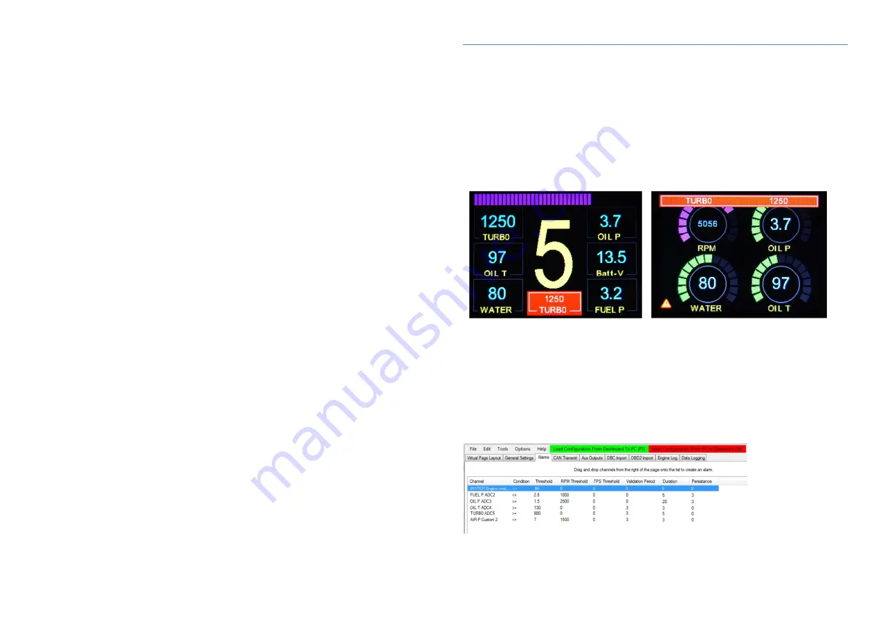
When an alarm is triggered a warning message is flashed on the screen, the size and position of which is 
determined by the type of page being viewed. For a text only page (page style 1), the alarm is displayed 
under the gear number and presents as an alternate flashing red/yellow box containing white text with the 
channel name and the current value. For dial gauge pages (page styles 3-9) the alarm is displayed as a 
flashing bar along the top of the page. 


Alarms remain visible until the channel causing the alarm returns to a safe value, or until it is acknowledged 
by the driver by pressing the alarm button. A brief press of the button will remove the alarm but leave a 
warning triangle icon visible. If the button is pressed momentarily while the icon is present then the alarm 
will be displayed again. Pressing and holding the button for 2 seconds will clear the alarm and prevent it 
from recurring until the dashboard is reset by power cycling. 

11.2 Adding & configuring alarms 

To add an alarm, select the Alarm tab at the top of the main window. Channels may then be dragged from 
the channel list on the right of the page and dropped onto the main window. A typical alarm configuration is 
shown below: 


The function of the alarm parameters are described on the following page: 

Summary of Contents for G-Dash Colour Dashboard

Page 1: ...e 12 o 7 4 Display properties Page 13 o 7 5 Display colours Page 13 o 7 6 Display limits Page 14 o 7 7 CAN data scaling Page 14 o 7 8 Configuring analogue input channels Page 14 o 7 9 Analogue scaling...

Page 2: ...2 x common pre defined channels such as RPM water temp oil temp oil pressure etc Up to 10 additional user defined custom CAN channels Up to 5 analogue channels 0 5v Linear or non linear analogue input...

Page 3: ...location to either side is acceptable Although the TFT display has a very wide viewing angle when mounted to one side it s recommended that the unit is angled towards the driver Optional mounting kit...

Page 4: ...xist then check through the Device Manager list looking for any unknown device that has a yellow triangle beside it This signifies that Windows knows that a device is connected but has failed to insta...

Page 5: ...file This makes dashboard channel setup a quick and simple task Click on the Import DBC file box or select Tools Import from DBC Further information can be found in section 8 of this user manual OBD2...

Page 6: ...nnel You can then rename the channel label to how you would like it to appear on the dash Keep the label as short as possible due to space limitations We recommend that labels for text display values...

Page 7: ...as half way around the gauge For example the normal engine coolant temperature may be 80 C but the ECU might transmit values between 20 and 200 Therefore we can set the display limits between 40 and...

Page 8: ...bc filename extension The dbc file uses a standardised format that the G Dash software can read The database file contains all the configuration information required to setup CAN channels without the...

Page 9: ...e of special request messages sent from the dashboard When you drag and drop a channel onto the list on the right hand side all the CAN parameters are automatically populated to enable the dash to tra...

Page 10: ...value before you can add a new gear Alternatively you can sample the current value from the gear channel by clicking the Sample box After the value is entered you can add a new gear and rename it as r...

Page 11: ...is triggers a warning message to flash up when a channel value falls outside of the acceptable range Multiple alarms are supported and are displayed in sequence The time each alarm is visible in the s...

Page 12: ...en circuit when not active and switched to ground when active They are capable of switching loads up to 2 Amps with a supply voltage up to 12v Note when connecting to digital inputs of other devices i...

Page 13: ...Intel To add data channels to the message frame move to the lower half of the window and you will see a list of 8 slots representing the 8 bytes of the message frame The top slot in the list represent...

Page 14: ...ddition to the engine log and the recording of maximum channel values the Geartronics G Dash has full on board data recording capability Retrieved data is viewed graphically in our own Dashview data a...

Page 15: ...from the standard Windows palette Scaling Min minimum displayed value Scaling Max maximum displayed value Filter used for smoothing a noisy trace Show Samples changes the trace from an interpolated li...

Page 16: ...ely 120ohms Incidentally when the bus is terminated correctly with 2 resistors you will measure approximately 60ohms when you conduct this test 32 The dashboard is supplied with the CAN terminators sw...

Reviews: