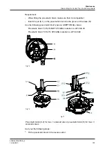
10.4.3 Removing the Solenoid Valves and the Control Plate
Fig.67
Requirement:
•
Observe the assignment of cables between the solenoid valve and the
interface module – solenoid valve Y1 to be connected to terminal Y1.1/Y1.2.
•
Only use solenoid valves specified in chapter “Technical data”.
Caution!
Risk of burns from the solenoid valve as a result of long switch-
on time and high ambient temperature
Risk of burns from the solenoid valve
► Allow to cool before dismantling.
Carry out the following steps:
1.
Disconnect the cables of the solenoid valve from the terminals of the interface
module (43).
2.
Undo the screws (66) and separate the solenoid valve (63) from the
pneumatic block (8).
3.
Undo the screws (65.1) and separate the control plate (65) from the
pneumatic block (8).
®
Done
Hint!
Fit the solenoid valves and control plate in the reverse order.
Lightly grease the seals before fitting them to prevent them from
falling out!
Maintenance
Dismantling the Control Top into its Components
430BAL010697EN_2
96
15.04.2020
Summary of Contents for T.VIS M-15
Page 6: ...430BAL010697EN_2 6 15 04 2020...
Page 53: ...Fig 27 Assembly and installation Electrical connections 430BAL010697EN_2 15 04 2020 53...
Page 55: ...Fig 28 Assembly and installation Electrical connections 430BAL010697EN_2 15 04 2020 55...
Page 119: ...Appendix 430BAL010697EN_2 15 04 2020 119...
Page 120: ......


