D
GB
F
E
3
96156-03.2016-DGb
Contents
Page
4
Compressor assembly
12
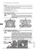
4.1 Storage and transportation
4.2 Setting up
4.3 Connecting the pipelines - solder system
4.4 Connecting the pipelines - cutting ring system
4.5 Pipes
4.6 Flange shut-off valves (HP/LP)
4.7 Option: cutting ring screw joint (HP/LP)
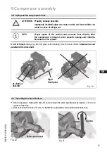
4.8 Laying suction and pressure lines
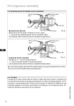
4.9 Operating the shut-off valves
4.10 Operating mode of the lockable service connections
4.11 Oil return
5
Electrical connection
17
5.1 Information for contactor and motor contactor selection
5.2 Standard motor, designed for direct or part winding start
5.3 Basic circuit diagram for part winding start -->
with MP10
5.4 Basic circuit diagram for part winding start -->
with INT69 G
5.5 Special motor: design for direct or star-delta start
5.6 Basic circuit diagram for star-delta start with special motor -->
with MP10
5.7 Electronic trigger unit MP10
5.8 Connection of the electronic trigger unit MP10
5.9 Functional test of the electronic trigger unit MP10
5.10 Basic circuit diagram for star-delta start with special motor -->
with INT69 G
5.11 Electronic trigger unit INT69 G
5.12 Connection of the electronic trigger unit INT69 G
5.13 Functional test of the electronic trigger unit INT69 G
5.14 Oil sump heater
6 Commissioning
34
6.1 Preparations for start-up
6.2 Pressure strength test
6.3 Leak test
6.4 Evacuation
6.5 Refrigerant charge
6.6 Start-up
6.7 Pressure switch
6.8 Decompression valves
6.9 Avoiding slugging
6.10 Filter dryer
7 Maintenance
38
7.1 Preparation
7.2 Work to be carried out
7.3 Accessories
7.4 Spare parts recommendation
7.5 Lubricants
7.6 Decommissioning
8
Technical data
40
9
Dimensions and connections
42
10 Declaration of installation
44
11 Service
45


