


42
D
GB
F
E
96156-03.2016-DGb
9
|
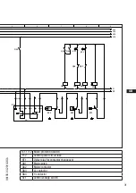
Dimensions and connections
Dimensions in mm
Fig. 32
Dimensions in ( ) = HGX34/110-4 (ML) (S) (SH) CO
2
T
HGX34/130-4 (ML) (S) (SH) CO
2
T
HGX34/150-4 ML CO
2
T
HGX34/170-4 ML CO
2
T
Dimensions in [ ] = HGX34/290-4 (ML) (S) (SH) CO
2
T
82
430
82
7,5
ca.250 (230) [260]
ca.
165
280
4x
12
364
[369]
DV
X
606 (547) [623]
7,5
ca.730 (670) [745]
H
D1
L B2
X2
F
X1
ca.710 (650) [725]
B2
O
J1
K
E
A2
150
330
4
1
0
ca.
ca.375 [420]
Typ / type
Teile-Nr. /
part-no.
Typ / type
Teile-Nr. /
part-no.
Typ / type
Teile-Nr. /
part-no.
Typ / type
Teile-Nr. /
part-no.
HGX34/110-4 ML CO2 T
10940
HGX34/150-4 ML CO2 T
10942
HGX34/190-4 MLCO2 T
10944
HGX34/230-4 ML CO2 T
10946
HGX34/110-4 S CO2 T
10814
HGX34/150-4 S CO2 T
10816
HGX34/190-4 S CO2 T
10818
HGX34/230-4 S CO2 T
10820
HGX34/110-4 SH CO2 T
10947
HGX34/150-4 SH CO2 T
10949
HGX34/190-4 SH CO2 T
10951
HGX34/230-4 SH CO2 T
10953
HGX34/130-4 ML CO2 T
10941
HGX34/170-4 ML CO2 T
10943
HGX34/210-4 ML CO2 T
10945
HGX34/290-4 ML CO2 T
11000
HGX34/130-4 S CO2 T
10815
HGX34/170-4 S CO2 T
10817
HGX34/210-4 S CO2 T
10819
HGX34/290-4 S CO2 T
11001
HGX34/130-4 SH CO2 T
10948
HGX34/170-4 SH CO2 T
10950
HGX34/210-4 SH CO2 T
10952
HGX34/290-4 SH CO2 T
11002
1.0850-10820.0
Halbhermetischer Verdichter HG / Semi-hermetic compressor HG
Maße in mm
Dimensions in mm
Änderungen vorbehalten
Subject to change without notice
Massenschwerpunkt
Centre of gravity
Maße in ( ) für HGX34/110+130-4 ML+S+SH CO2 T und HGX34/150+170-4 ML CO2 T
Dimensions in ( ) for HGX34/110+130-4 ML+S+SH CO2 T and HGX34/150+170-4 ML CO2 T
Maße in [ ] für HGX34/290-4 ML+S+SH CO2 T
Dimensions in [ ] for HGX34/290-4 ML+S+SH CO2 T
0g
Maße und Anschlüsse mit Absperrventile
measures and connections with shut-off valve
Anschlüsse /
Connections
HGX34/110
- 230
HGX34/290
SV
Saugabsperrventil, Rohr
(L/SW, SR)*
mm - Zoll
28 - 1 1/8"
35 - 1 3/8"
Suction line valve, tube
(L/SW, SR)*
mm - inch
DV
Druckabsperrventil, Rohr
(L/SW, SR)*
mm - Zoll
22 - 7/8"
28 - 1 1/8"
Discharge line valve, tube
(L/SW, SR)*
mm - inch
A
Anschluss Saugseite, nicht absperrbar
Zoll
7/16“ UNF
Connection suction side, not lockable
inch
A1
Anschluss Saugseite, absperrbar
Zoll
7/16“ UNF
Connection suction side, lockable
inch
A2
Anschluss Saugseite, nicht absperrbar
Zoll
1/8“ NPTF
Connection suction side, not lockable
inch
B
Anschluss Druckseite, nicht absperrbar
Zoll
7/16“ UNF
Connection discharge side, not lockable
inch
B1
Anschluss Druckseite, absperrbar
Zoll
7/16“ UNF
Connection discharge side, lockable
inch
B2
Anschluss Druckseite, nicht absperrbar
Zoll
1/8“ NPTF
Connection discharge side, not lockable
inch
D1
Anschluss Ölrückführung vom Ölabscheider
Zoll
1/4“ NPTF
Connection oil return from oil separator
inch
E
Anschluss Öldruckmanometer
Zoll
1/8“ NPTF
Connection oil pressure gauge
inch
F
Ölablass
mm
M26x1,5
Oil drain
H
Stopfen Ölfüllung
mm
M22x1,5
Oil charge plug
J1
Ölsumpfheizung
mm
15
oil sump heater
K
Schauglas
Zoll
1 1/8"-18 UNEF
Sight glass
inch
L
Anschluss Wärmeschutzthermostat
Zoll
1/8“ NPTF
Connection thermal protection thermostat
inch
O
Anschluss Ölspiegelregulator
mm
1/2" NPTF
Connection oil level regulator
X1
Schraderanschluss, Saugseite
Zoll
7/16“ UNF
Connection for schrader valve, suction side
inch
X2
Schraderanschluss, Druckseite
Zoll
7/16“ UNF
Connection for schrader valve, Discharge side
inch
(L/SW, SR)* = Löt-/Schweissanschluss, Schneidring
(L/SW. SR)* = solder/welding connection, cutting ring
A
A1
X
SV
Alt.bezug /
Part-No.
F
E
D
C
A
F
E
D
C
4
1
A
B
5
6
7
8
1
2
3
4
5
6
7
8
Zeichn.-Nr. / Drawing no. :
B
3
2
112747
z
über / above
Freigabe / Approved
Extranet:
-
-
Alt.supply:
Der Lieferant muss sicherstellen, dass die Ware
in einwandfreiem Zustand angeliefert wird
(Korrosionsschutz, Verpackung für sicheren
Layh
Allgemeintoleranzen / General tolerances
Drawing-No.
bis / up to
Dok-
ID
:
Maßstab /
±0.1
y
x
w
u
t
packaging for safe transportation).
model or design.
-
in proper conditions (corrosion prevention,
DIN ISO 2768-mK
Ra Rz
02.05.12
Ersatz für / replacement for:
The supplier has to ensure the delivery of parts
Transport).
prohibited. Offenders will be held liable for the
Dimension
Passung / Clearance
Baumustergeprüft / Type examination:
-
-
K.-Auftrag / C.-Task:
Projektleiter / Project leader:
120
400
±0.5
0.5
6
GEA Bock GmbH - Benzstraße 7 - 72636 Frickenhausen - Germany - www.bock.de
-
-
-
Unbemaßte Radien / Undimensioned radii:
-
Bearb. / Edited
Datum / Date
payment of damages. All rights reserved in the event
Änd.-Nr. / Mod-No.
Werkstoff (Zeile 2+3 alternativ) /
Base part, Raw part:
-
-
Geprüft / Appr.
Name
Datum / Date
02.05.12
Material (Line 2+3 alternative):
Ausgangsteil, Rohteil /
Workpiece edges
DIN ISO 13715
Erstellt / Drawn
Geprüft / Verified
Büttner
Zuder
1/3
Oberflächenbehandlung, Härte / Treatment of surface, Hardness:
02.05.12
Werkstückkanten /
Page:
400
Benennung / Description:
±0.8
1000
30
6
-
±0.3
120
30
-
Blatt /
±0.2
of the grant of a patent, utility
/
DIN EN ISO 1302
Zust. / Rev.
Gußtoleranzen / General casting tolerances:
Gewicht / Weight: (kg)
Zeichnungs-Nr. /
Indication of surface texture
Scale:
%
MC- HGX34/230-4 S CO2 T
Rz 25
Rz 160
25
0,05 Rz 1,6
0,3
0,7
1,6
2
Rz 16
6,3 Rz 63
Rz 6,3
Rz 12,5
Status:
-
-
Frei (CAD)
Nein / No
10820 .0
05.07.13
21.10.13
20.11.13
20.11.13
08.01.14
20.02.14
05.09.14
Zuder
Zuder
Zuder
Zuder
Zuder
Zuder
Zuder
0c | Vereinheitlichung der Ausführungen ML, S und SH, SV 70084 ersetzt durch 70136
0d | Umstellung auf opt. Motoren, O-Ring 50286 ersetzt durch Dichtung 60040
0d | Umstellung der Kolbenringe, Flanschabsperrventile als Zubehör
0d | Abdeckbleche entfernt, Rückschlagventil 50988 ersetzt durch 07803
0e | betrifft Blatt 2
0f | betrifft Blat 2
0g | Verdichter HGX34/290-4 ML+S+SH und Impedanzrohr in Zeichnung aufgenommen
8695
8553,8614
8776,8556
8401
8776
8579
9099
Keuerleber
Keuerleber
Keuerleber
Keuerleber
Keuerleber
Keuerleber
Keuerleber
MK- HGX34/230-4 S CO2 T
-
0850
1.
Kunde / Customer:
-
s
Weitergabe sowie Vervielfältigung dieses Dokuments,
Verwertung und Mitteilung seines Inhalts sind ver-
boten, soweit nicht ausdrücklich gestattet. Zuwider-
handlungen verpflichten zu Schadenersatz. Alle
Rechte für den Fall der Patent-, Gebrauchsmuster-
oder Geschmacksmustereintragung vorbehalten.
The reproduction, distribution and utilization of this
document as well as the communication of its
contents to others without express authorization is
Maß
Oberflächenangaben /
Teile-Nr. /
Layh
B1 B
Schwingungsdämpfer
Vibration absorbers
3
0
50
10
M
2
5
82
430
82
7,5
ca.250 (230) [260]
ca.
165
280
4x
12
364
[369]
DV
X
606 (547) [623]
7,5
ca.730 (670) [745]
H
D1
L B2
X2
F
X1
ca.710 (650) [725]
B2
O
J1
K
E
A2
150
330
4
1
0
ca.
ca.375 [420]
Typ / type
Teile-Nr. /
part-no.
Typ / type
Teile-Nr. /
part-no.
Typ / type
Teile-Nr. /
part-no.
Typ / type
Teile-Nr. /
part-no.
HGX34/110-4 ML CO2 T
10940
HGX34/150-4 ML CO2 T
10942
HGX34/190-4 MLCO2 T
10944
HGX34/230-4 ML CO2 T
10946
HGX34/110-4 S CO2 T
10814
HGX34/150-4 S CO2 T
10816
HGX34/190-4 S CO2 T
10818
HGX34/230-4 S CO2 T
10820
HGX34/110-4 SH CO2 T
10947
HGX34/150-4 SH CO2 T
10949
HGX34/190-4 SH CO2 T
10951
HGX34/230-4 SH CO2 T
10953
HGX34/130-4 ML CO2 T
10941
HGX34/170-4 ML CO2 T
10943
HGX34/210-4 ML CO2 T
10945
HGX34/290-4 ML CO2 T
11000
HGX34/130-4 S CO2 T
10815
HGX34/170-4 S CO2 T
10817
HGX34/210-4 S CO2 T
10819
HGX34/290-4 S CO2 T
11001
HGX34/130-4 SH CO2 T
10948
HGX34/170-4 SH CO2 T
10950
HGX34/210-4 SH CO2 T
10952
HGX34/290-4 SH CO2 T
11002
1.0850-10820.0
Halbhermetischer Verdichter HG / Semi-hermetic compressor HG
Maße in mm
Dimensions in mm
Änderungen vorbehalten
Subject to change without notice
Massenschwerpunkt
Centre of gravity
Maße in ( ) für HGX34/110+130-4 ML+S+SH CO2 T und HGX34/150+170-4 ML CO2 T
Dimensions in ( ) for HGX34/110+130-4 ML+S+SH CO2 T and HGX34/150+170-4 ML CO2 T
Maße in [ ] für HGX34/290-4 ML+S+SH CO2 T
Dimensions in [ ] for HGX34/290-4 ML+S+SH CO2 T
0g
Maße und Anschlüsse mit Absperrventile
measures and connections with shut-off valve
Anschlüsse /
Connections
HGX34/110
- 230
HGX34/290
SV
Saugabsperrventil, Rohr
(L/SW, SR)*
mm - Zoll
28 - 1 1/8"
35 - 1 3/8"
Suction line valve, tube
(L/SW, SR)*
mm - inch
DV
Druckabsperrventil, Rohr
(L/SW, SR)*
mm - Zoll
22 - 7/8"
28 - 1 1/8"
Discharge line valve, tube
(L/SW, SR)*
mm - inch
A
Anschluss Saugseite, nicht absperrbar
Zoll
7/16“ UNF
Connection suction side, not lockable
inch
A1
Anschluss Saugseite, absperrbar
Zoll
7/16“ UNF
Connection suction side, lockable
inch
A2
Anschluss Saugseite, nicht absperrbar
Zoll
1/8“ NPTF
Connection suction side, not lockable
inch
B
Anschluss Druckseite, nicht absperrbar
Zoll
7/16“ UNF
Connection discharge side, not lockable
inch
B1
Anschluss Druckseite, absperrbar
Zoll
7/16“ UNF
Connection discharge side, lockable
inch
B2
Anschluss Druckseite, nicht absperrbar
Zoll
1/8“ NPTF
Connection discharge side, not lockable
inch
D1
Anschluss Ölrückführung vom Ölabscheider
Zoll
1/4“ NPTF
Connection oil return from oil separator
inch
E
Anschluss Öldruckmanometer
Zoll
1/8“ NPTF
Connection oil pressure gauge
inch
F
Ölablass
mm
M26x1,5
Oil drain
H
Stopfen Ölfüllung
mm
M22x1,5
Oil charge plug
J1
Ölsumpfheizung
mm
15
oil sump heater
K
Schauglas
Zoll
1 1/8"-18 UNEF
Sight glass
inch
L
Anschluss Wärmeschutzthermostat
Zoll
1/8“ NPTF
Connection thermal protection thermostat
inch
O
Anschluss Ölspiegelregulator
mm
1/2" NPTF
Connection oil level regulator
X1
Schraderanschluss, Saugseite
Zoll
7/16“ UNF
Connection for schrader valve, suction side
inch
X2
Schraderanschluss, Druckseite
Zoll
7/16“ UNF
Connection for schrader valve, Discharge side
inch
(L/SW, SR)* = Löt-/Schweissanschluss, Schneidring
(L/SW. SR)* = solder/welding connection, cutting ring
A
A1
X
SV
Alt.bezug /
Part-No.
F
E
D
C
A
F
E
D
C
4
1
A
B
5
6
7
8
1
2
3
4
5
6
7
8
Zeichn.-Nr. / Drawing no. :
B
3
2
112747
z
über / above
Freigabe / Approved
Extranet:
-
-
Alt.supply:
Der Lieferant muss sicherstellen, dass die Ware
in einwandfreiem Zustand angeliefert wird
(Korrosionsschutz, Verpackung für sicheren
Layh
Allgemeintoleranzen / General tolerances
Drawing-No.
bis / up to
Dok-
ID
:
Maßstab /
±0.1
y
x
w
u
t
packaging for safe transportation).
model or design.
-
in proper conditions (corrosion prevention,
DIN ISO 2768-mK
Ra Rz
02.05.12
Ersatz für / replacement for:
The supplier has to ensure the delivery of parts
Transport).
prohibited. Offenders will be held liable for the
Dimension
Passung / Clearance
Baumustergeprüft / Type examination:
-
-
K.-Auftrag / C.-Task:
Projektleiter / Project leader:
120
400
±0.5
0.5
6
GEA Bock GmbH - Benzstraße 7 - 72636 Frickenhausen - Germany - www.bock.de
-
-
-
Unbemaßte Radien / Undimensioned radii:
-
Bearb. / Edited
Datum / Date
payment of damages. All rights reserved in the event
Änd.-Nr. / Mod-No.
Werkstoff (Zeile 2+3 alternativ) /
Base part, Raw part:
-
-
Geprüft / Appr.
Name
Datum / Date
02.05.12
Material (Line 2+3 alternative):
Ausgangsteil, Rohteil /
Workpiece edges
DIN ISO 13715
Erstellt / Drawn
Geprüft / Verified
Büttner
Zuder
1/3
Oberflächenbehandlung, Härte / Treatment of surface, Hardness:
02.05.12
Werkstückkanten /
Page:
400
Benennung / Description:
±0.8
1000
30
6
-
±0.3
120
30
-
Blatt /
±0.2
of the grant of a patent, utility
/
DIN EN ISO 1302
Zust. / Rev.
Gußtoleranzen / General casting tolerances:
Gewicht / Weight: (kg)
Zeichnungs-Nr. /
Indication of surface texture
Scale:
%
MC- HGX34/230-4 S CO2 T
Rz 25
Rz 160
25
0,05 Rz 1,6
0,3
0,7
1,6
2
Rz 16
6,3 Rz 63
Rz 6,3
Rz 12,5
Status:
-
-
Frei (CAD)
Nein / No
10820 .0
05.07.13
21.10.13
20.11.13
20.11.13
08.01.14
20.02.14
05.09.14
Zuder
Zuder
Zuder
Zuder
Zuder
Zuder
Zuder
0c | Vereinheitlichung der Ausführungen ML, S und SH, SV 70084 ersetzt durch 70136
0d | Umstellung auf opt. Motoren, O-Ring 50286 ersetzt durch Dichtung 60040
0d | Umstellung der Kolbenringe, Flanschabsperrventile als Zubehör
0d | Abdeckbleche entfernt, Rückschlagventil 50988 ersetzt durch 07803
0e | betrifft Blatt 2
0f | betrifft Blat 2
0g | Verdichter HGX34/290-4 ML+S+SH und Impedanzrohr in Zeichnung aufgenommen
8695
8553,8614
8776,8556
8401
8776
8579
9099
Keuerleber
Keuerleber
Keuerleber
Keuerleber
Keuerleber
Keuerleber
Keuerleber
MK- HGX34/230-4 S CO2 T
-
0850
1.
Kunde / Customer:
-
s
Weitergabe sowie Vervielfältigung dieses Dokuments,
Verwertung und Mitteilung seines Inhalts sind ver-
boten, soweit nicht ausdrücklich gestattet. Zuwider-
handlungen verpflichten zu Schadenersatz. Alle
Rechte für den Fall der Patent-, Gebrauchsmuster-
oder Geschmacksmustereintragung vorbehalten.
The reproduction, distribution and utilization of this
document as well as the communication of its
contents to others without express authorization is
Maß
Oberflächenangaben /
Teile-Nr. /
Layh
B1 B
Schwingungsdämpfer
Vibration absorbers
3
0
50
10
M
2
5
Centre of gravity
82
430
82
7,5
ca.250 (230) [260]
ca.
165
280
4x
12
364
[369]
DV
X
606 (547) [623]
7,5
ca.730 (670) [745]
H
D1
L B2
X2
F
X1
ca.710 (650) [725]
B2
O
J1
K
E
A2
150
330
4
1
0
ca.
ca.375 [420]
Typ / type
Teile-Nr. /
part-no.
Typ / type
Teile-Nr. /
part-no.
Typ / type
Teile-Nr. /
part-no.
Typ / type
Teile-Nr. /
part-no.
HGX34/110-4 ML CO2 T
10940
HGX34/150-4 ML CO2 T
10942
HGX34/190-4 MLCO2 T
10944
HGX34/230-4 ML CO2 T
10946
HGX34/110-4 S CO2 T
10814
HGX34/150-4 S CO2 T
10816
HGX34/190-4 S CO2 T
10818
HGX34/230-4 S CO2 T
10820
HGX34/110-4 SH CO2 T
10947
HGX34/150-4 SH CO2 T
10949
HGX34/190-4 SH CO2 T
10951
HGX34/230-4 SH CO2 T
10953
HGX34/130-4 ML CO2 T
10941
HGX34/170-4 ML CO2 T
10943
HGX34/210-4 ML CO2 T
10945
HGX34/290-4 ML CO2 T
11000
HGX34/130-4 S CO2 T
10815
HGX34/170-4 S CO2 T
10817
HGX34/210-4 S CO2 T
10819
HGX34/290-4 S CO2 T
11001
HGX34/130-4 SH CO2 T
10948
HGX34/170-4 SH CO2 T
10950
HGX34/210-4 SH CO2 T
10952
HGX34/290-4 SH CO2 T
11002
1.0850-10820.0
Halbhermetischer Verdichter HG / Semi-hermetic compressor HG
Maße in mm
Dimensions in mm
Änderungen vorbehalten
Subject to change without notice
Massenschwerpunkt
Centre of gravity
Maße in ( ) für HGX34/110+130-4 ML+S+SH CO2 T und HGX34/150+170-4 ML CO2 T
Dimensions in ( ) for HGX34/110+130-4 ML+S+SH CO2 T and HGX34/150+170-4 ML CO2 T
Maße in [ ] für HGX34/290-4 ML+S+SH CO2 T
Dimensions in [ ] for HGX34/290-4 ML+S+SH CO2 T
0g
Maße und Anschlüsse mit Absperrventile
measures and connections with shut-off valve
Anschlüsse /
Connections
HGX34/110
- 230
HGX34/290
SV
Saugabsperrventil, Rohr
(L/SW, SR)*
mm - Zoll
28 - 1 1/8"
35 - 1 3/8"
Suction line valve, tube
(L/SW, SR)*
mm - inch
DV
Druckabsperrventil, Rohr
(L/SW, SR)*
mm - Zoll
22 - 7/8"
28 - 1 1/8"
Discharge line valve, tube
(L/SW, SR)*
mm - inch
A
Anschluss Saugseite, nicht absperrbar
Zoll
7/16“ UNF
Connection suction side, not lockable
inch
A1
Anschluss Saugseite, absperrbar
Zoll
7/16“ UNF
Connection suction side, lockable
inch
A2
Anschluss Saugseite, nicht absperrbar
Zoll
1/8“ NPTF
Connection suction side, not lockable
inch
B
Anschluss Druckseite, nicht absperrbar
Zoll
7/16“ UNF
Connection discharge side, not lockable
inch
B1
Anschluss Druckseite, absperrbar
Zoll
7/16“ UNF
Connection discharge side, lockable
inch
B2
Anschluss Druckseite, nicht absperrbar
Zoll
1/8“ NPTF
Connection discharge side, not lockable
inch
D1
Anschluss Ölrückführung vom Ölabscheider
Zoll
1/4“ NPTF
Connection oil return from oil separator
inch
E
Anschluss Öldruckmanometer
Zoll
1/8“ NPTF
Connection oil pressure gauge
inch
F
Ölablass
mm
M26x1,5
Oil drain
H
Stopfen Ölfüllung
mm
M22x1,5
Oil charge plug
J1
Ölsumpfheizung
mm
15
oil sump heater
K
Schauglas
Zoll
1 1/8"-18 UNEF
Sight glass
inch
L
Anschluss Wärmeschutzthermostat
Zoll
1/8“ NPTF
Connection thermal protection thermostat
inch
O
Anschluss Ölspiegelregulator
mm
1/2" NPTF
Connection oil level regulator
X1
Schraderanschluss, Saugseite
Zoll
7/16“ UNF
Connection for schrader valve, suction side
inch
X2
Schraderanschluss, Druckseite
Zoll
7/16“ UNF
Connection for schrader valve, Discharge side
inch
(L/SW, SR)* = Löt-/Schweissanschluss, Schneidring
(L/SW. SR)* = solder/welding connection, cutting ring
A
A1
X
SV
Alt.bezug /
Part-No.
F
E
D
C
A
F
E
D
C
4
1
A
B
5
6
7
8
1
2
3
4
5
6
7
8
Zeichn.-Nr. / Drawing no. :
B
3
2
112747
z
über / above
Freigabe / Approved
Extranet:
-
-
Alt.supply:
Der Lieferant muss sicherstellen, dass die Ware
in einwandfreiem Zustand angeliefert wird
(Korrosionsschutz, Verpackung für sicheren
Layh
Allgemeintoleranzen / General tolerances
Drawing-No.
bis / up to
Dok-
ID
:
Maßstab /
±0.1
y
x
w
u
t
packaging for safe transportation).
model or design.
-
in proper conditions (corrosion prevention,
DIN ISO 2768-mK
Ra Rz
02.05.12
Ersatz für / replacement for:
The supplier has to ensure the delivery of parts
Transport).
prohibited. Offenders will be held liable for the
Dimension
Passung / Clearance
Baumustergeprüft / Type examination:
-
-
K.-Auftrag / C.-Task:
Projektleiter / Project leader:
120
400
±0.5
0.5
6
GEA Bock GmbH - Benzstraße 7 - 72636 Frickenhausen - Germany - www.bock.de
-
-
-
Unbemaßte Radien / Undimensioned radii:
-
Bearb. / Edited
Datum / Date
payment of damages. All rights reserved in the event
Änd.-Nr. / Mod-No.
Werkstoff (Zeile 2+3 alternativ) /
Base part, Raw part:
-
-
Geprüft / Appr.
Name
Datum / Date
02.05.12
Material (Line 2+3 alternative):
Ausgangsteil, Rohteil /
Workpiece edges
DIN ISO 13715
Erstellt / Drawn
Geprüft / Verified
Büttner
Zuder
1/3
Oberflächenbehandlung, Härte / Treatment of surface, Hardness:
02.05.12
Werkstückkanten /
Page:
400
Benennung / Description:
±0.8
1000
30
6
-
±0.3
120
30
-
Blatt /
±0.2
of the grant of a patent, utility
/
DIN EN ISO 1302
Zust. / Rev.
Gußtoleranzen / General casting tolerances:
Gewicht / Weight: (kg)
Zeichnungs-Nr. /
Indication of surface texture
Scale:
%
MC- HGX34/230-4 S CO2 T
Rz 25
Rz 160
25
0,05 Rz 1,6
0,3
0,7
1,6
2
Rz 16
6,3 Rz 63
Rz 6,3
Rz 12,5
Status:
-
-
Frei (CAD)
Nein / No
10820 .0
05.07.13
21.10.13
20.11.13
20.11.13
08.01.14
20.02.14
05.09.14
Zuder
Zuder
Zuder
Zuder
Zuder
Zuder
Zuder
0c | Vereinheitlichung der Ausführungen ML, S und SH, SV 70084 ersetzt durch 70136
0d | Umstellung auf opt. Motoren, O-Ring 50286 ersetzt durch Dichtung 60040
0d | Umstellung der Kolbenringe, Flanschabsperrventile als Zubehör
0d | Abdeckbleche entfernt, Rückschlagventil 50988 ersetzt durch 07803
0e | betrifft Blatt 2
0f | betrifft Blat 2
0g | Verdichter HGX34/290-4 ML+S+SH und Impedanzrohr in Zeichnung aufgenommen
8695
8553,8614
8776,8556
8401
8776
8579
9099
Keuerleber
Keuerleber
Keuerleber
Keuerleber
Keuerleber
Keuerleber
Keuerleber
MK- HGX34/230-4 S CO2 T
-
0850
1.
Kunde / Customer:
-
s
Weitergabe sowie Vervielfältigung dieses Dokuments,
Verwertung und Mitteilung seines Inhalts sind ver-
boten, soweit nicht ausdrücklich gestattet. Zuwider-
handlungen verpflichten zu Schadenersatz. Alle
Rechte für den Fall der Patent-, Gebrauchsmuster-
oder Geschmacksmustereintragung vorbehalten.
The reproduction, distribution and utilization of this
document as well as the communication of its
contents to others without express authorization is
Maß
Oberflächenangaben /
Teile-Nr. /
Layh
B1 B
Schwingungsdämpfer
Vibration absorbers
3
0
50
10
M
2
5
Anti-vibration
pads
Dimensions and connections with shut-off valves


