


22
D
GB
F
E
96156-03.2016-DGb
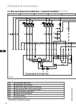
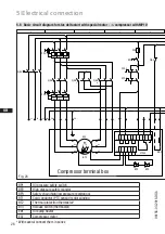
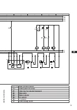
5.4 Basic circuit diagram for part winding start --> compressor with INT69 G
Οnderung
6
0
Datum
Name
Datum
Bearb.
Gepr.
Norm
1
20.02.2009
Kelich
27.05.2015
Urspr.
2
Ers. f.
3
Ers. d.
4
PW INT69 HG44/56
5
6
7
BOCK COMPRESSORS
8
=
+
9
Bl.
6.2
Bl.
6.2
6.1
Anschlußkasten Verdichter
BT1
INT69
BP1
P-Öl
QA1
L1
L2
L3
N
PE
FC1.1
I>
I>
I>
QA2
1U1
1V1
1W1
PE
EC1
M
Y/YY
2U1
2V1
2W1
FC1.2
I>
I>
I>
QA3
FC1.1
FC1.2
FC2
SF1
BP2
P>
QA2
BP3
P
QA2
KF1
KF1
6.8
6.2.8
QA2
EB1
L1.1
L2.1
L3.1
L1.2
N
PE
QA3
11
12
14
L
N
B1 B2
BT3
BT2
Θ
T2
N
L
M
S
QA2
PE
BT2
Θ
Fig. 25
5
|
Electrical connection
Compressor terminal box
BP1
Oil pressure safety switch
BP2
High pressure safety monitor
BP3
Safety chain (high/low pressure monitoring)
BT1
Cold conductor (PTC sensor) motor winding
BT2
Thermal protection thermostat*
BT3
Release switch (thermostat)
EB1
Oil sump heater
EC1
Compressor motor
* With several connect them in series


