


D
GB
F
E
15
96156-03.2016-DGb
4.9 Operating the shut-off valves
Before opening or closing the shut-off valve, release the valve spindle seal by approx. ¼ of a turn
counter-clockwise.
After activating the shut-off valve, re-tighten the adjustable valve spindle seal clockwise.
Fig. 20
Fig. 21
Valve spindle seal
release
tighten
4
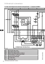
|
Compressor assembly
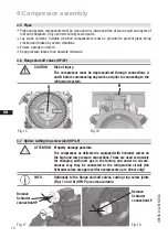
Fig. 19
Rigid
fixed point
As short as
possible
4.8 Laying suction and pressure lines
A rule of thumb:
Always lay the first pipe section starting from the shut-off valve
downwards and
parallel to the drive shaft.
ATTENTION Property damage possible.
Improperly installed pipes can cause cracks and tears which can
result in a loss of refrigerant.
INFO
Proper layout of the suction and pressure lines directly after
the compressor is integral to the smooth running and vibration
behaviour of the system.


