background image

20

 D
 GB
 F
 E

96422-07.2018-DGbFEI

CO

streaming 

out

Fig. 15


6

|

 Commissioning

  Check that the safety and protection devices (pressure switch, motor protection, electrical contact 

protection measures, etc.) are functioning properly.

  Switch on the compressor and let it run for at least 10 minutes.
 

The machine should reach a state of equilibrium.

  Check the 

oil level

: The oil level must be visible in the sight glass.

  After a compressor is replaced, the oil level must be checked again. If the level is too high, oil 

must be drained off (danger of oil liquid shocks; reduced capacity of the refrigerating system).

WARNING

Ensure that both shut-off valves are open before starting the 

compressor!

ATTENTION

If larger quantities of oil have to be topped up, there is a risk of oil 
impact effects. If this is the case, check the oil return!

6.6 Start-up

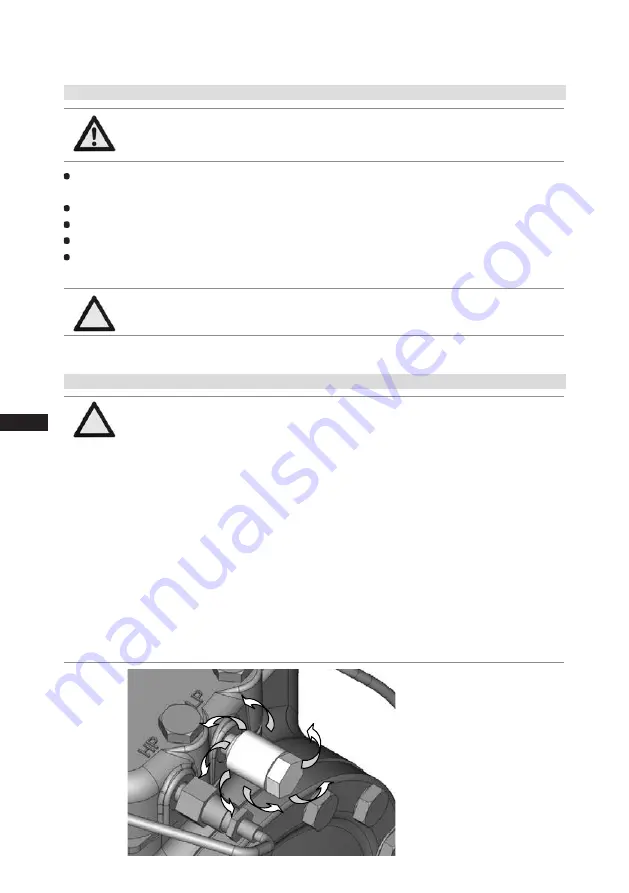
6.7  Decompression valves

ATTENTION

The compressor is fitted with two decompression valves. One valve 

each on the suction and discharge side. If excessive pressures are 

reached, the valves open and prevent further pressure increase.

Thereby CO

2

 is blown off to the ambient!

In the event that a pressure relief valve activates repeatedly, check 

valve and replace if necessary as during blow-off extreme condi-

tions can occure, which may result in a permanent leak. Always 
check system for refrigerant loss after activation of pressure relief 
valve!

The decompression valves do not replace any pressure switches 
and the additional safety valves in the system. Pressure switches 

must always be installed in the system and designed or adjusted in 

accordance with EN 378-2 or appropriate safety standards.

Failure to observe can result in risk of injury from CO

2

 streaming 

out of the two decompression valves!

Summary of Contents for HGX22e/85-4 S CO2

Page 1: ...e 105 4 S CO2 HGX22e 130 4 S CO2 HGX34e 145 4 S CO2 HGX34e 170 4 S CO2 HGX34e 210 4 S CO2 HGX34e 255 4 S CO2 Assembly instructions 96422 07 2018 Gb Translation of the original instructions GEA Bock HG...

Page 2: ...f the compressor can result in serious or fatal injury Observe the safety instructions contained in these instructions These instructions must be passed onto the end customer along with the unit in wh...

Page 3: ...12 5 1 Information for contactor and motor contactor selection 5 2 Connection of the driving motor 5 3 Circuit diagram for direct start 230 V 400 V Y 5 4 Electronic trigger unit INT69 G 5 5 Connection...

Page 4: ...ing which enable personnel to assemble install maintain and repair refrigeration and air conditioning systems Personnel must be capable of assessing the work to be carried out and recognising any pote...

Page 5: ...tallations are designed or adjusted in accordance with EN 378 2 or appropriate safety standards These assembly instructions describe the standard version of the compressor named in the title manufactu...

Page 6: ...atively low temperature level Oil pump independent of direction of rotation for reliable and safe oil supply One pressure relief valve each on the low and high pressure side which vent into the atmosp...

Page 7: ...re g High pressure side 50 Hz 60 Hz 6 Voltage circuit frequency 7 Nominal rotation speed 8 Displacement 9 Voltage circuit frequency 10 Nominal rotation speed 11 Displacement 12 Oil type filled at the...

Page 8: ...in the diagrams Please note the significance of the shaded areas Thresholds should not be selected as design or continuous operation points Permissible ambient temperature 20 C 60 C Max permissible di...

Page 9: ...sation Do not store in a corrosive dusty vaporous atmosphere or in a com bustible environment Sun protection If the compressor is set up outdoors it has to be protected from direct sunlight 4 3 Pipe c...

Page 10: ...standart millimetre and inch dimensions can be used The connection diameters of the shut off valves are rated for maximum compressor output The actual required pipe cross section must be matched to th...

Page 11: ...lockable service connections Fig 10 Opening the shut off valve Spindle turn to the left counter clockwise as far as it will go Shut off valve completely opened service connection closed Fig 11 Opening...

Page 12: ...st comply with the local safety regulations and established specifications e g VDE as well as the manufacturer s specifications Motor protection switches are required Motor contactors feed lines fuses...

Page 13: ...L3 L1 L2 Electrical connection Raccordement lectrique Y 96027 11 06 DGbF Niedere Spannung Low voltage Bas voltage Y Hohe Spannung High voltage Haut voltage L3 L1 L2 L3 L1 L2 L1 L2 L3 L1 L2 L3 5 2 Con...

Page 14: ...7 6 5 4 3 2 1 FC1 1 I I I 1 2 QA2 3 4 5 6 EC1 3 M 5 3 Circuit diagramm for direct start 230 V 400 V Y Fig 12 BP2 High pressure safety controller BP3 Safety chain high low pressure monitoring BT2 Therm...

Page 15: ...GbFEI BP1 P QA2 BP2 P L1 1 L2 1 L3 1 L1 2 N PE BT3 BT2 BT2 EB1 FC1 1 Motor protection switch FC2 Control power circuit fuse INT69 G Electronic trigger unit INT69 G QA1 Main switch QA2 Mains contactor...

Page 16: ...The relay switching output is executed as a floating changeover contact This electrical circuit operates according to the quiescent current principle i e the relay drops into a the idle position and d...

Page 17: ...50 120 W PTC heater adjusting ATTENTION The oil sump heater must generally be connected and operated Relay position INT69 G B2 12 14 11 Fig 14 5 6 Function test of the trigger unit INT69 G Before com...

Page 18: ...tats are mandatory on the installation side 6 3 Leak test Carry out the leak test on the refrigerating plant in accordance with EN 378 2 or a corresponding safety standard while always observing the m...

Page 19: ...during and after the filling process the shut off point of the low pressure switch should be set to a value of at least 5 2 bar A refrigerant supplement which may become necessary after start up can...

Page 20: ...ct effects If this is the case check the oil return 6 6 Start up 6 7 Decompression valves ATTENTION The compressor is fitted with two decompression valves One valve each on the suction and discharge s...

Page 21: ...mperature is 30 C The system must reach a state of equilibrium Particularly in critical systems e g several evaporator points measures are recommended such as replacement of liquid traps solenoid valv...

Page 22: ...restart Relieve compressor of system pressure Prevent air from infiltrating the system After maintenance has been performed Connect safety switch Evacuate compressor Release switch on lock 7 2 Work to...

Page 23: ...st drop in pressure to prevent oil from exiting with it If the compressor is unpressurized remove the piping on the pressure and suction side e g dismantling of the shut off valve etc and remove the c...

Page 24: ...64 83 1 2 3 2 4 220 240 V 380 420 V Y 3 50 Hz 265 290 V 440 480 V Y 3 60 Hz 4 3 All specifications are based on the average of the voltage range For solder connections Tolerance 10 relative to the mea...

Page 25: ...2 22 3 26 8 44 8 25 9 15 8 178 103 105 1 2 3 2 4 220 240 V 380 420 V Y 3 50 Hz 265 290 V 440 480 V Y 3 60 Hz 4 3 All specifications are based on the average of the voltage range For solder connection...

Page 26: ...ces Gewicht Weight kg Zeichnungs Nr Indication of surface texture Oberfl chenbehandlung H rte Treatment of surface Hardness Scale MC HGX22e 130 4 S CO2 Rz 25 Rz 160 25 0 05 Rz 1 6 0 3 0 7 1 6 2 Rz 16...

Page 27: ...s reserved in the event nd Nr Mod No Gepr ft Appr 30 104 9 0 3 120 30 0 2 of the grant of a patent utility Zust Rev Gu toleranzen General casting tolera Gewicht Weight kg 6 Nein No Weitergabe sowie Ve...

Page 28: ...dards referenced A partly completed machine may only be put into operation when it has been established that the machine into which the partly completed machine is to be installed conforms to the regu...

Page 29: ...questions about installation operation and accessories please contact our technical service or specialist wholesaler and or our representative The GEA service team can be contacted by phone with a tol...

Page 30: ...ne 49 0 7022 9454 0 Fax 49 0 7022 9454 137 info gea com gea com GEA Group is a global engineering company with multi billion euro sales and operations in more than 50 countries Founded in 1881 the com...

Reviews: