background image

Copyright © FEBrUAry, 2010 By grizzly indUstriAl, inC.

Warning: no portion of this manual may be reproduced in any shape

 or form Without the Written approval of grizzly industrial, inc.

For modEls mAnUFACtUrEd sinCE 02/10 #Cr12612  printEd in ChinA

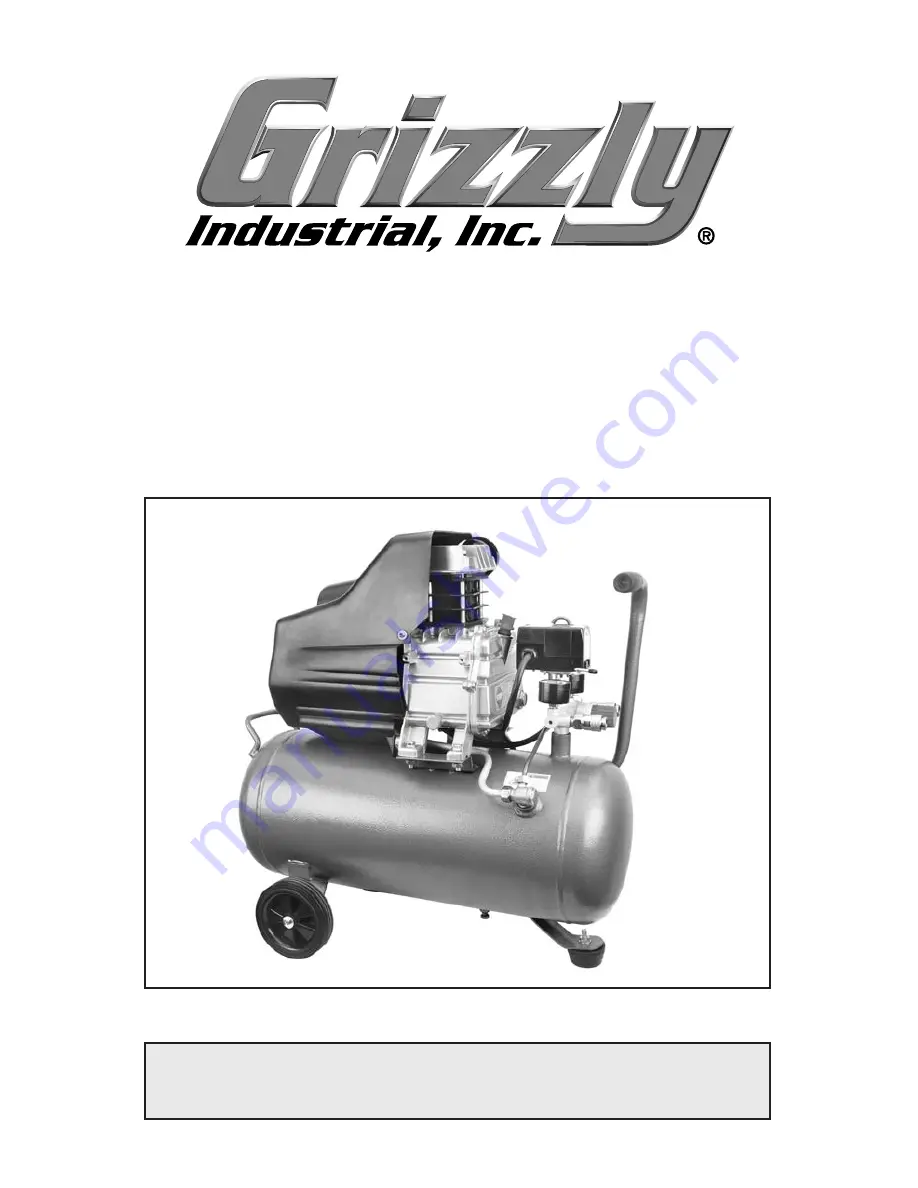
model t21888


2.5 hp, 

6.3 gallon compressor

instruction manual

Summary of Contents for T21888

Page 1: ... Warning No portion of this manual may be reproduced in any shape or form without the written approval of Grizzly Industrial inc For models manufactured SINCE 02 10 CR12612 printed IN CHINA MODEL T21888 2 5 HP 6 3 GALLON COMPRESSOR INSTRUCTION MANUAL ...

Page 2: ... personal protective equipment The manufacturer will not be held liable for injury or property damage from negligence improper training machine modifications or misuse Some dust created by power sanding sawing grinding drilling and other construction activities contains chemicals known to the State of California to cause cancer birth defects or other reproductive harm Some examples of these chemic...

Page 3: ... Unpacking 8 Assembly 8 Placement 8 Test Run Break In 9 SECTION 3 OPERATIONS 10 Pressure Regulator Use 10 Operation 11 Accessories 12 SECTION 4 MAINTENANCE 13 Schedule 13 Draining Tank 14 Pressure Relief Valve Test 14 SECTION 5 SERVICE 15 Troubleshooting 15 Changing Oil 18 Check Valve 18 Fixing Air Leaks 19 Pressure Switch 20 Storage 21 Parts Breakdown 22 Parts List 23 Warranty 24 ...

Page 4: ...al please write to us at the following address Grizzly Industrial Inc C O Technical Documentation P O Box 2069 Bellingham WA 98227 2069 E Mail manuals grizzly com Most importantly we stand behind our tools If you have any service questions or parts requests please call or write us at the location listed below Grizzly Industrial Inc 1203 Lycoming Mall Circle Muncy PA 17756 Phone 570 546 9663 Fax 80...

Page 5: ...ow Remember that safety messages by themselves do not eliminate danger and are not a substitute for proper accident prevention measures Indicates a potentially hazardous situation which if not avoided MAY result in minor or moderate injury It may also be used to alert against unsafe practices Indicates a potentially hazardous situation which if not avoided COULD result in death or serious injury I...

Page 6: ...N TOOLS WITH CARE Keep tools lubricated and clean for best and safest performance Follow instructions for lubricating and chang ing accessories 16 DO NOT FORCE TOOL It will do the job better and safer at the rate for which it was designed 17 CHECK FOR DAMAGED PARTS BEFORE USING Check for bind ing and alignment of parts broken parts part mounting loose bolts and any other conditions that may affect...

Page 7: ...AVOID BURNS The motor and air supply pipe get hot and can cause burns if touched DO NOT touch these compressor parts if the unit has been running within the last 30 minutes 4 AIR LINE AND POWER CORD SAFETY Ruptured air lines or severed electrical cords can blind or electrocute you Make sure your air hose has a PSI rating that exceeds the maximum PSI of your compressor is in good condi tion and is ...

Page 8: ...reaker on an existing circuit with one of higher amperage without consulting a qualified electrician to ensure compli ance with wiring codes If you are unsure about the wiring codes in your area or you plan to connect your machine to a shared circuit consult a qualified electrician Minimum Circuit Requirement 20 Amp Figure 1 Typical type 5 15 plug and receptacle Grounding Prong is Longest of the T...

Page 9: ...the power cord must be properly connected to the grounding prong on the plug likewise the outlet must be properly installed and grounded All elec trical connections must be made in accor dance with local codes and ordinances Extension Cords To reach the work area use additional air hoses instead of extension cords The use of extension cord with a compressor can cause the cords to overheat catch fi...

Page 10: ...top of the crankcase and add air compres sor oil into the hole When full the oil level should be in the center of the sight glass Figure 3 Oil cap and sight glass location Sight Glass Oil Fill Cap Placement The contacts of the compressor pres sure switch spark when cycling the compressor motor ON and OFF If any flammable gases are near the switch ignition and explosion may occur resulting in sever...

Page 11: ... level sight glass to make sure the crankcase oil is at the full mark 4 Connect the compressor to the power supply 5 Leave the drain valve Figure 5 open push the switch to the down position or the ON position and allow the com pressor to free run for 15 minutes for a no load break in before closing the drain valve and allowing it to build air pressure Figure 4 ON OFF lever ON OFF Lever Figure 5 Dr...

Page 12: ...ontrol the air supply to your tool 1 Adjust the regulator knob shown in Figure 7 to set the PSI that will be delivered to your tool Turn the knob clockwise to increase the pressure or counterclockwise to decrease the pres sure Pressure Regulator Use ACCIDENTAL START HAZARD Disconnect before service or tool changes AIR PRESSURE HAZARD Never exceed max PSI rating for tool EYE EAR INJURY HAZARD Wear ...

Page 13: ...rheat Figure 8 Thermal overload reset Thermal Overload Reset To use your air compressor 1 Put on safety glasses 2 Make sure the compressor lever is in the down or the OFF position as shown in Figure 9 Figure 9 ON OFF lever ON OFF Lever 3 Close the tank drain valve 4 Double check the oil level sight glass shown in Figure 10 to make sure the crankcase oil is at the full mark Figure 10 Sight glass lo...

Page 14: ...ay gun is critical for high quality spraying results This filter is rated at 150 PSI maximum air pressure and has a 1 4 NPT air inlet G8114 3 8 x 25 Ft Air Hose G8115 3 8 x 50 Ft Air Hose G8116 3 8 x 100 Ft Air Hose We recommend dedicating an air hose for spraying use only keeping it clean and free of water and oil by using a filter on the incoming end Multi purpose red rubber air hose is flexible...

Page 15: ...rtain the safety protection you wear meet the appro priate standards of the American National Standards Institute ANSI Weekly If used daily perform the following com pressor checks each week otherwise check these items once a month 1 Remove and blow out the air filter Figure 15 from the inside out then re install The air compressor will turn ON auto matically when it is set on AUTO When performing...

Page 16: ... safety valve Pressure Relief Valve Water will accumulate in the tank depend ing on usage and humidity Drain water from the tank daily to increase the lifespan of the compressor and air tools Draining Tank Figure 16 Tank drain valve Draining the air from the tank will be extremely loud and debris may be blown into your eyes from the floor Wear safety glasses and ear protec tion when draining the t...

Page 17: ...ol then push reset 3 Replace start capacitor 4 Inspect and repair all connections on motor for loose or shorted termi nals or worn insulation 5 Replace or adjust the pressure switch Page 20 6 Push in reset button 7 Replace motor Motor overheats and thermal overload turns motor OFF 1 Compressor and motor have restricted air flow 2 Air filter clogged 3 Thermal overload switch has tripped 1 Clean cyl...

Page 18: ... 8 Inspect and replace pump piston rings Pressure relief valve stays open and motor won t stop running 1 Pressure switch adjusted too high 2 Faulty pressure switch unit is trying to overpres sure the tank 3 Faulty pressure relief valve 1 Adjust the pressure switch Page 20 2 Turn compressor OFF unplug from power sup ply and empty tank DO NOT USE until switch is replaced 3 Relief valve is reliev ing...

Page 19: ... with actual com pressor oil 6 Worn compressor piston rings or valves Rebuild or replace compressor Air tools have watery discharge or get cold and freeze up with ice during use 1 Compressor tank needs draining 2 Ambient environment has too much humidity 3 In line water separator is full if used 1 Drain compressor tank Page 14 2 Install in line air dryer and water separator 3 Drain water separator...

Page 20: ... and cause the valve to leak or prevent the compressor from building air To fix the check valve 1 DISCONNECT THE COMPRESSOR FROM POWER AND DRAIN ALL AIR FROM THE TANK 2 Using a 19mm wrench remove the cap shown in Figure 19 from the check valve Figure 19 Check valve assembly Cap NOTICE The oil fill cap releases crankcase pressure through a small hole in the top of the cap Keep this hole unclogged o...

Page 21: ... ALL AIR FROM THE TANK 2 Unscrew the fitting that is leaking 3 Clean and apply Teflon tape or liquid thread sealant to the fitting threads 4 Clean and chase the threads with the appropriate thread tap 5 Re install the fitting to the compressor 3 Inspect the seal ring and diaphragm Figure 20 for damage and dirt Figure 20 Check valve assembly Seal Ring 4 Replace any damaged parts and clean any dirt ...

Page 22: ...mpressor switch is in the OFF position 4 Using a 2 Phillips screwdriver remove the switch cover shown in Figure 21 and hinge back the cover and set it aside If the minimum and maximum tank pressure settings both have to be raised or lowered at the same time then the cut in and cut out adjustment screw must be adjusted Turn the cut out adjustment screw Figure 22 a half turn clockwise to increase bo...

Page 23: ...tore the air compressor in its normal operating position in a dry and pro tected area Storage Water will condense in the air com pressor tank when the compressor is in operation Water left in the tank can cause the tank to weaken and corrode increasing the risk of tank rupture Always disconnect the air hose from tools whenever not in use or while servicing During maintenance a tool connected to ai...

Page 24: ... 46 3 4 2 1 40 39 37 35 9 13 14 15 18 19 20 21 22 23 24 25 26 27 28 29 30 31 32 33 34 36 38 41 42 54 53 5 51 52 55 79 73 71 70 72 74 76 77 78 83 84 56 58 59 60 61 63 64 65 66 67 68 80 81 69 62 63 82 10 11 86 87 86 87 43 45 44 88 89 Parts Breakdown ...

Page 25: ...1888064 FITTING NUT 19 PT21888019 CYLINDER BODY 65 PT21888065 STEEL EXHAUST PIPE 20 PT21888020 DOWEL PIN 2 94 X 6 56MM 66 PT21888066 CHECK VALVE 21 PT21888021 INPUT REED VALVE 67 PT21888067 FITTING NUT 22 PT21888022 VALVE GASKET 68 PT21888068 COPPER UNLOADING PIPE 23 PT21888023 VALVE BODY 69 PT21888069 AXLE 24 PT21888024 OUTPUT REED VALVE 70 PW04M FLAT WASHER 10MM 25 PT21888025 VALVE STOP 71 PT218...

Page 26: ... death injuries to persons or property or for incidental contingent special or consequential damages arising from the use of our products To take advantage of this warranty contact us by mail or phone and give us all the details We will then issue you a Return Authorization Number which must be clearly posted on the outside as well as the inside of the carton We will not accept any item back witho...

Page 27: ...ars ____2 8 Years ____8 20 Years ____20 Years 6 How many of your machines or tools are Grizzly ____0 2 ____3 5 ____6 9 ____10 7 Do you think your machine represents a good value ____Yes ____No 8 Would you recommend Grizzly Industrial to a friend ____Yes ____No 9 Would you allow us to use your name as a reference for our customers in your area Note We never use names more than 3 times ____Yes ____N...

Page 28: ...c p o box 2069 bellingham wa 98227 2069 tape along edges please do not staple Name________________________________ Street________________________________ City______________State______Zip_______ Send a Grizzly Catalog to a friend Place Stamp Here ...

Reviews: