background image


OPERATING INSTRUCTIONS 


GRASSO SYSTEM CONTROL 

FOR TWO STAGE CHILLER/ PACKAGES WITH SCREW 

COMPRESSORS 


_805011_om_gsc_sp2_gbr_1_.doc 

 13  

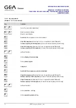
Key 

Function 

Call up the 

menu overview


Return

 or cancel input 


Acknowledge

, reset failure and warning 


Confirm input


Press the button once for display of a 

help text


Switch over to the 

2nd keyboard level


Cursor keys


Functions of the F1 ... F4 buttons


These functions are only available if the symbols can be seen in the display. 

Back

 to previous display 


Go to the 

menu item

 described 


Move

 o next display 


Standard functions of the Shift button


Change between the 

possible selections


 + 

 or 


Alter the 

display contrast


 + 


Summary of Contents for Grasso

Page 1: ..._805011_om_gsc_sp2_gbr_1_ doc 1 Grasso System Control for two stage Chiller Packages with Screw Compressors Operating Instructions...

Page 2: ...tion may be copied or published by means of printing photocopying microfilm or otherwise without prior written consent of Grasso This restriction also applies to the corresponding drawings and diagram...

Page 3: ...SORS _805011_om_gsc_sp2_gbr_1_ doc 3 SYMBOLS USED IN THIS MANUAL Danger This is an important warning Non observance these warnings can cause accidents with relevant damages on persons or serious damag...

Page 4: ......

Page 5: ...cription of the Grasso System Control 8 1 2 1 View 8 1 2 2 Lamps Push buttons 10 1 2 3 Operator terminal 11 1 2 3 1 Key assignment 12 1 2 3 2 Call up table of contents 14 1 2 4 Status displays 15 1 3...

Page 6: ......

Page 7: ...ACKAGES WITH SCREW COMPRESSORS _805011_om_gsc_sp2_gbr_1_ doc 7 TABLE OF FIGURES fig 1 View of outside of switchgear cabinet 8 fig 2 View of inside of switchgear cabinet 9 fig 3 GSC operator terminal 1...

Page 8: ...st important information for the operator The indexes are not identical with those of the GSC User Manual The index X X X under the headings of this operating instruction refers to the matching chapte...

Page 9: ...TWO STAGE CHILLER PACKAGES WITH SCREW COMPRESSORS _805011_om_gsc_sp2_gbr_1_ doc 9 fig 2 View of inside of switchgear cabinet 1 Profibus DP DP coppler 2 Bus Terminal 3 Type of Power Supply 4 Emergency...

Page 10: ...essor drive motor is switched off Yellow indicator light Warning This lamp flashes if an operating condition reaches a preset value Warning Pre alarm Detection of this warning can be acknowledged at t...

Page 11: ...apter 1 2 in user manual The operator terminal is the interface between the operator and the control unit All switching operating and control actions are carried out via this operator terminal fig 3 G...

Page 12: ...apacity control only Start LP compressor Press key for 5 sec in operation mode Manual Increase capacity of LP compressor in case of manual capacity control only without function Call up display of act...

Page 13: ...e and warning Confirm input Press the button once for display of a help text Switch over to the 2nd keyboard level Cursor keys Functions of the F1 F4 buttons These functions are only available if the...

Page 14: ...e to the Date Time menu 1 2 3 2 Call up table of contents Chapter 1 2 3 in user manual key A list of the available menus is then displayed To get to the table of contents press the Number Title Help t...

Page 15: ...ause serious damage to the screw compressor unit or chiller 1 2 4 Status displays Chapter 1 3 in User Manual To get to the status display views press the key several times or press the key and then Th...

Page 16: ...eted Running Compressor motor running in Delta or startup has been completed Package Chiller in operation Psuc Limitation A capacity limitation is active suction pressure too low reduce output solenoi...

Page 17: ...g LP Text display flashes Italic lettering Text appears as static text Normal lettering The overall status of the compressor unit is displayed with the LEDs in and Key Colour Status Explanation Green...

Page 18: ...hile MAINS ON Peripheral error in the internal peripheral functions Further information about the malfunction that has occured can be read out of the diagnosis memory using the PG BATF red Battery err...

Page 19: ...4th row the status message is shown By scrolling with the cursor keys and all active alarms and warnings are displayed 1 4 2 No alarm signal and the compressor will not start Chapter 6 5 in user manu...

Page 20: ...HILLER PACKAGES WITH SCREW COMPRESSORS 20 _805011_om_gsc_sp2_gbr_1_ doc 1 4 3 Restart following Alarms Chapter 7 2 in user manual fig 5 Restart following Alarms Caution It is not possible to restart t...

Page 21: ...w press the key or in the case that several alarms have occurred simultaneously Step Procedure 1 Call up the Alarms menu by pressing the key 2 Select the View menu item for the alarms by pressing the...

Page 22: ......

Reviews: