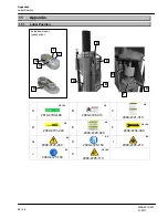
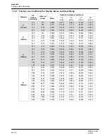
background image

Appendix

Consistency test

2008-9015-001
01-2017

64 / 66

11.3

Consistency test

GEA Houle determined the following method to verify if the viscosity of the liquid
manure is suitable for this product.

1. Set a pail on a level surface and install a 24” [60cm] round plate at the center

of the pail.

2. Fill a second pail with homogenized liquid manure and slowly pour it in the

center of the plate until it overflows all around the plate. Remain close to the
plate when pouring the liquid manure.

3. Wait one minute.

4. Measure the thickness of the liquid manure at the center of the plate to

determine the consistency.

Summary of Contents for CA8 Series

Page 1: ...3 Pump Electric Pumps Operation Manual Installation Instructions Original instructions 2008 9015 001 01 2017 gea com...

Page 2: ...a 22 4 4 Motor specification 26 4 5 Control panel specifications 27 4 6 Acoustic emission 27 4 7 Hydraulic hoses 27 4 8 Bolt Torque Chart 28 4 9 Lubricant specifications 28 5 Handling and Assembly 29...

Page 3: ...fications Required for Maintenance Work 52 9 2 Safety Instructions for Maintenance 52 9 3 Scheduled maintenance responsibilities 52 9 4 Motor support threaded bolts lubrication 54 9 5 Bearing housing...

Page 4: ...developments in the data and illustrations in this manual Reproductions translations and copies of any kind including extracts require written authorization from the manufacturer This manual is suppli...

Page 5: ...manuals have a part number The 4 middle digits specify the language of the instruction manual Language Language Language 9000 German 9013 Dutch 9032 Serbian 9001 English United Kingdom 9015 English No...

Page 6: ...ecessary please contact your nearest dealer There is a comprehensive dealer Internet search function on our website at the following address www gea farmtechnologies com European Contact Information G...

Page 7: ...07 Safety of machinery Guards General requirements for the design and construction of fixed and movable guards EN 12100 1 2009 10 Safety of machinery Basic concepts general principles for design EN 12...

Page 8: ...01 01 2017 8 66 Authorized person for compiling and handing over technical documentation Josef Schr er GEA Farm Technologies GmbH Siemensstra e 25 27 D 59199 B nen 49 0 2383 93 70 Drummondville 13 sep...

Page 9: ...RCHASER AND DOES NOT APPLY IN THE EVENT THAT THE EQUIPMENT IS SOLD OR OTHERWISE TRANSFERRED 1 5 2 Condition of the limited warranty The Company through its GEA authorized dealers only hereinafter refe...

Page 10: ...tions including without limitation damages caused by fire lightning flood or other natural disaster damages caused by the use of sand litter or other abrasive or inadequate material including without...

Page 11: ...ECT CONSEQUENTIAL INCIDENTAL PUNITIVE OR EXEMPLARY DAMAGES IN ANY KIND OR CHARACTER INCLUDING INDIRECT COSTS LOSS OF PRODUCTION LOSS OF REVENUES OR PROFITS AND OTHER DISBURSEMENTS WHICH MAY OCCUR Some...

Page 12: ...ed by Web site Canada Canadian Centre for Occupational Health and Safety www ccohs ca USA Occupational Safety and Health Administration www osha gov European Union European Agency for Safety and Healt...

Page 13: ...ndicates an immediate threat to the lives or health of personnel Death or serious injury may result if the danger is not avoided Warning The indication Warning signals danger to life or health of pers...

Page 14: ...near this product unless they are performing instructions included in this manual When near this product keep body parts such as hands feet hair as well as clothing away from dangerous parts such as...

Page 15: ...workers of those rules maintenance and methods Qualified personnel Qualified personnel refers to those having obtained the academic knowledge of a specific field of work This personnel has followed a...

Page 16: ...s product The labels must remain in place and legible at all times Replace when damaged Refer to the part number for the appropriate label Danger Toxic gases American model Manure produces toxic gases...

Page 17: ...operator s manual for safety information before service and maintenance European model Part no 2099 4725 130 Always turn off and lock main power before service and maintenance European model Part no 2...

Page 18: ...ications provided in this manual The equipment is not designed to use any other type of motor than those listed Improper motor performance may result in damage to the equipment and or motor The manufa...

Page 19: ...hanges Planned changes must be approved by the manufacturer in writing Any unauthorized modifications to the product will invalidate the warranty and may invalidate the manufacturer s declaration or i...

Page 20: ...Data 4 1 Pump geometric data 3 Pump 3 High Pressure 3 Compact Impeller diameter 5 7 8 150mm 6 9 16 167mm 6 13 16 173mm 7 1 16 180mm 8 1 4 210mm 9 1 2 241mm 5 7 8 150mm 6 9 16 167mm Pump height 102 174...

Page 21: ...Technical Data Minimum pit opening 2008 9015 001 01 2017 21 66 4 2 Minimum pit opening 3 pump 3 compact pump 3 high pressure...

Page 22: ...um manure consistency 6 35mm Maximum pressure 1 79 bar 26 psi Operating temperature 5 C 41 F minimum Note The pulley ratio and pump performances indicated in the following tables are standard combinat...

Page 23: ...7 23 66 4 3 1 3 pump Pumping Head Transfer rate Motor size SAE 3HP 5HP 7 5HP Motor size metric 2 2KW 3 7KW 5 5KW Pump drive type Direct drive Frequency 60 Hz only Motor RPM 1760 Maximum manure consist...

Page 24: ...017 24 66 4 3 2 3 compact pump Pumping Head Transfer rate Motor size SAE 3HP 5HP Motor size metric 2 2KW 3 7KW Pump drive type Direct drive Frequency 60 Hz only Motor RPM 1760 Maximum manure consisten...

Page 25: ...igh pressure pump Pumping Head Transfer rate Motor size SAE 5HP 7 5HP 10HP Motor size metric 3 7KW 5 5KW 7 5KW Pump drive type Pulley drive Direct drive Frequency 50 Hz 60 Hz Motor RPM 1450 1760 Maxim...

Page 26: ...cooling TEFC IC 411 Totally Enclosed Fan Cooled Vibration class No special requirements Insulation 155 F to 130 B Duty type S1 continuous operation Direction or rotation Bi directional Rated motor vol...

Page 27: ...ectrotechnology EN 60617 Graphical symbols be equipped with an emergency stop be protected by a lockable disconnect switch cut off switch meet all motor specifications provided in this manual meet loc...

Page 28: ...4ft lb 73Nm 78ft lb 106Nm 114ft lb 155Nm 154ft lb 209Nm 257ft lb 349Nm 382ft lb 518Nm 587ft lb 796Nm SAE 8 MCAS 14ft lb 19Nm 29ft lb 39Nm 47ft lb 64Nm 78ft lb 106Nm 119ft lb 161Nm 169ft lb 229Nm 230ft...

Page 29: ...performed by a certified electrician Read the section Safety Personnel qualifications 5 2 Safety instructions for handling and assembly Warning Do not stand under or near a lifted load a falling load...

Page 30: ...n bolts and anchor bolts at the specified torque 5 3 3 To be provided by the customer Safety fences installed around the equipment reservoir to prevent fall An electric motor meeting the technical spe...

Page 31: ...0mm 1 3 4 45mm 2 1 4 57mm 2 1 4 57mm 4 1 4 108mm Hmin 4 101mm 4 101mm 4 101mm 4 101mm 6 152mm Concrete drill bit diameter Dia 3 8 10mm 1 2 13mm 1 2 13mm 1 2 13mm 3 4 19mm Torque 20ft lb 25Nm 40ft lb 5...

Page 32: ...mp handling Warning Do not stand under or near a lifted load a falling load can cause death Attention To lift the equipment use a lifting device with a minimum capacity of 3000 lbs 1400 kg Choose most...

Page 33: ...support 1 on the concrete floor using anchor bolts Assemble the support 2 on the pump frame 3 and tighten the adjustment bolt 4 Lower the pump into the pit and secure the support 2 to the support base...

Page 34: ...alling the U bolt make sure the U bolt does not compress grease lines Position the pump against the support 8 while making sure it stays vertical Attach the pump to the support using the U bolt 9 Make...

Page 35: ...es Step 1 Check the control panel electric components Before performing any electric connection tighten the screws of all the electric components inside the control panel Make sure all wires are prope...

Page 36: ...nt Attention To lift this product use a lifting device with a minimum lifting capacity of 1000 lbs 450 kg Attention GEA provides specifications and wiring diagrams related to Baldor motor s For any ot...

Page 37: ...bolt pattern on the support and secure using lock washers and nuts Align the motor to the two half joints 1 3 using the spacers and shims provided Tighten the assembly Check the alignment of the chai...

Page 38: ...bly Electric motor installation 2008 9015 001 01 2017 38 66 5 9 2 Pulley drive European 3 high pressure pump only 1 3 2 4 Bolt the motor 1 to the support 2 Make sure the support hinge 3 is locked with...

Page 39: ...t off switch must be connected to the control panel to shutdown or energize the entire cleaning system through the control panel only Attention Make sure the motor rotates in the direction indicated o...

Page 40: ...g 4 bolts and washers 2 3 1 Legend A Segment to be removed to fit on large diametre motor shaft Assemble keys 4 hubs 5 and pulleys 6 on the shafts 7 Dry mount assembly only never use lubricants or ant...

Page 41: ...ing table contains torque requirements specified by the manufacturer The information may not reflect the current torque requirements Refer to manufacturer for more information Hub set screw torque Set...

Page 42: ...n to the belt The belts must deflect roughly 1 2 13mm when applying pressure of 12 lbs 5kg midway 2 between the pulleys Check pulley alignment and readjust if required 1 2 Install the safety guard 3 o...

Page 43: ...3 Connection to an outside evacuation line To ensure proper drainage of the evacuation line connect the pump outlet to a PVC pipe long enough to provide a minimum of 5 slope towards the main pit Conn...

Page 44: ...onnel qualification required for initial commissioning Initial commissioning must be performed by trained personnel in accordance with the safety instructions Read the section Safety Personnel qualifi...

Page 45: ...onnections are secured A visual inspection is performed to ensure there are no leaks signs of distortion or defective parts The equipment component provided by the owner comply with the specifications...

Page 46: ...stration form must be returned to GEA Farm Technologies Canada Inc Division GEA Houle to validate the warranty Declaration of conformity and CE mark only necessary for European Union member states A d...

Page 47: ...Section Safety 7 3 Transferring mode 7 3 1 Pump without agitation nozzle Start the pump using the control panel 7 3 2 Pump with agitation nozzle optional Attention Stop the motor of the pump before sw...

Page 48: ...levers are locked at desired position before starting the motor STEP 1 Set the directional valve in agitation mode Unscrew the locking handle 1 Pull up the valve control lever 2 Tighten the locking ha...

Page 49: ...adjustment handle Set the nozzle height adjustment handle 6 up to raise the agitation nozzle or set it down to lower the agitation nozzle Tighten the locking handle 5 in position Start the pump using...

Page 50: ...ersonnel in accordance with the safety instructions Read the Section Safety Personnel Qualifications 8 2 Safety Instructions for Troubleshooting Warning Shutdown is required shut the main power supply...

Page 51: ...irectional valve damaged and jammed in agitation mode Repair or replace defective parts Obstruction in the impeller intake Contact your dealer Pump is working without reaching performance Improper man...

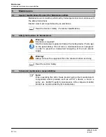
Page 52: ...tdown is required Shut the main power supply and lock with a locking device Post a sign on the panel stating Do not turn on maintenance work in progress in order to prevent an inadvertent energizing o...

Page 53: ...lubrication X Bearing housing lubrication Check the bolts torque X Check the motor belt tension if applicable X Visual inspection X X Upper bearing lubrication X Maintenance to be performed by a deale...

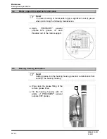
Page 54: ...performing the following maintenance Apply PRECISION general purpose EP2 grease on each threaded rod of the motor support 9 5 Bearing housing lubrication Note Adding grease into the bearing housing pr...

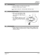
Page 55: ...the motor belt tension Make sure the belts deflect roughly 1 2 13mm when applying 12 lbs 5kg of pressure midway between the pulleys Use adjustment screw 1 on the motor support to adjust belt tension...

Page 56: ...unit wipe clean the bearing and grease immediately to prevent premature wear Wipe clean the grease fitting 1 Slowly add 2 grams of PRECISION general purpose EP2 grease while the bearing runs if possi...

Page 57: ...specially qualified personnel in accordance with the safety instructions Read the section Safety Personnel qualifications 10 2 Safety instructions for decommissioning Read the section Safety 10 3 Fina...

Page 58: ...sition F D E C B D A K G H I J European model pulley drive A 2010 4700 400 US EU B 2099 4720 010 US C 2099 4721 010 US D 2099 4701 240 US E 2099 4720 020 US F 2099 4700 390 US EU G 2099 4725 240 EU H...

Page 59: ...f the storage pit In SAE it is expressed in feet In metric it is expressed in meters 11 2 3 Manure consistency The manure consistency is the viscosity of a well agitated slurry A test must be performe...

Page 60: ...METRIC 3 4 6 8 10 12 15 75mm 100mm 150mm 200mm 250mm 300mm 350mm 45 PVC elbow 9 12 18 24 30 36 45 3 m 3 5 m 5 5 m 7 5 m 9 m 11 m 14 m 90 PVC elbow 9 32 48 64 7 5 m 10 m 14 5 m 19 5 m 45 Houle steel el...

Page 61: ...9 0 0224 0 0329 0 0480 600 2280 0 0233 0 0265 0 0314 0 0461 0 0673 700 2650 0 0310 0 0353 0 0418 0 0613 0 0895 8 200mm 500 1890 0 0041 0 0047 0 0055 0 0081 0 0118 700 2650 0 0076 0 0087 0 0103 0 0151...

Page 62: ...412 500 1890 0 0215 0 0246 0 0291 0 0427 0 0623 600 2280 0 0302 0 0344 0 0408 0 0598 0 0873 700 2650 0 0402 0 0458 0 0542 0 0795 0 1161 800 3030 0 0514 0 0586 0 0694 0 1018 0 1486 900 3410 0 0639 0 07...

Page 63: ...0 USGPM 800 lpm 45 PVC elbow 5 1 52m x 0 1117 0 559 0 17m F 210 USGPM 800 lpm PVC pipe 400 122m x 0 1117 44 68 13 6m SUM of each total 50 69 15 45m ELEVATION X 12 3 7m TOTAL PUMPING HEAD of the transf...

Page 64: ...a pail on a level surface and install a 24 60cm round plate at the center of the pail 2 Fill a second pail with homogenized liquid manure and slowly pour it in the center of the plate until it overfl...

Page 65: ...otive Engineers USA United States of America WWW World Wide Web Units Explanation Units Explanation A ampere kg kilogram AC alternative current kPa kilopascal cm centimeter kW kilowatt degree km h kil...

Page 66: ...c J2A 0C6 1 819 477 5565 www gea com We live our values Excellence Passion Integrity Responsibility GEA versity GEA Group is a global engineering company with multi billion euro sales and operations i...

Reviews: