D
GB
F
E
I
27
96463-08.2019-DGbFEIRu
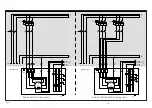
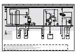
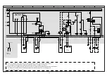
Fig. 20
Οnderung
2.e
0
Datum
Name
Datum
Bearb.
Gepr.
Norm
1
18.05.2006
bauknecht
13.10.2017
Urspr.
2
Ers. f.
3
Ers. d.
4
Schaltplan ATEX HH4, 5, 6
Direkt INT
V1.1
5
6
7
BOCK COMPRESSORS
8
=
+
9
Bl.
3.f
Bl.
3.1
2.f
Der Schaltplan ist nur ein Systemschema, zur Anordnung und Reihenfolge der Sicherheitskette, ohne Störungsmeldungen und Montageanordnung
(ob im oder außerhalb vom EX-Bereich).
Bei der Montage von Geräten sind die Sicherheitsausführungen der entsprechenden Montagezone zu beachten.
Die Typenschildangaben- und Betriebsanleitungen vom Hersteller der zu verwendenden Bauteile sind Unbedingt zu beachten.
KF4
INT69 EX2
FA1
BP5
FA2
Externe
Freigabe LR
Potentialfrei
Störung
Sicherheitskette
L1
L2
L3
N
PE
FC2.1
SF1
FC1.1
XSS
1
1
3
2
4 PA
A1
A2
KF3
P-öl
Kriwan
1
3
or
2
4
br
rot
13
14
QA2
PE
PE
8
BT3
A2
A1
KF1
Max.
90sec
16
15
KF2
18
16
15
KF1
A1
A2
QA2
18
PE
PE
PE
FC2.2
23
24
QA2
9
8
EB1
10
10
19
20
11
LR
P
12
L1
L2
L3
N
PE
PE
PE
12
11
KF3
14
PE
12
11
14
BP2
P>
PE
PE
PE
2
4
5
3
6
1
2
3
4
FB1
Δ
I
7
1 2
11
12
14
L
N
XKK
3 6
7
9
24V
A1
A2
X1
KF2
A1
A2
X1
2.e.7
A1
A2
X1
3.1.6
15 2.c.7
15 2.e.6
15 .6
15 3.1.6
15 3.c.6
15 3.e.6
15 3.f.6
16
2.c.7
16
2.e.6
16
.6
16
3.1.6
16
3.c.6
16
3.e.6
16
3.f.6
18
2.c.7
18
2.e.6
18
.6
18
3.1.7
18
3.c.7
18
3.e.7
18
3.f.7
12
11
14
BP1
P<
XKK D 1
XKK D 2
XKK D 3
XKK D 4
The circuit diagram is a system scheme for assignment and order of the safety chain, without
error messages and installation arrangement (whether inside or outside the Ex zone).
When devices are installed, the safety regulations of the corresponding installation zone must be followed.
The rating plate information and operating manual from the manufacturer of the components
to be used must always be observed.
Voltage-free
Safety
chain fault
External
release LR
P oil
Kriwan

