D
GB
F
E
I
21
96463-08.2019-DGbFEIRu
5
|
Electrical connection
DANGER
Risk of electric shock! High voltage!
Only carry out work when the electrical system is disconnected
from the power supply!
5 Electrical connection
ATTENTION
When attaching accessories with an electrical cable, a minimum
bending radius of 3 x the cable diameter must be maintained for
laying the cable.
INFO
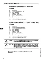
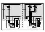
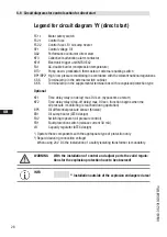
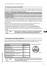
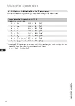
Connect the compressor motor according to the circuit diagram
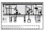
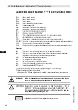
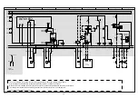
(s. fig. 19-21 or sticker inside the terminal box). Comply with local
safety regulations for electrical work, safety standards (within the EU:
EN 60204, EN 60335 among others) and regulations for setting up
electrical systems in explosion-endangered areas (within the EU: IEC /
EN 60079-14 among others).
Avoid damage to cable fittings, since otherwise operational safety can
be impaired. Lay the cable so that the fitting to the terminal box will
not loosen itself. If necessary (e.g. installation that is not twist free),
protection against loosening can be achieved through check nuts or
appropriate adhesive. Avoid abrasion points on cables.
For cable lead-through at the terminal box, use suitable Ex cable
screw connections in the correct protective version (see name plate).
Use strain relief. Avoid abrasion points on cables.
Install all switching devices outside the explosion-endangered area.
Motor contactors, feed lines and fuses are to be rated according to the
maximum operating current (see name plate). Recommendations for
contactor and motor protection selection are included in the table at
the end of the „Electrical system“ chapter 5.2.
Do not separate contacts 1 + 2 of the motor thermistors under voltage.
Compare the details for voltage and frequency on the nameplate with
the details for the electricity mains supply. The motor may only be
connected if these details match.
Use a motor protector switch. It should be set to the rated motor current
and checked.
For the installation of phases L1, L2 and L3 to line-up terminals U1, V1
and W1,
no
solid wire may be used.
Cross section for connection of line-up terminals U1, V1 and W1 =
6 - 35 mm².
Cross section for connection of line-up terminals 1, 2, 3 and 4 =
max. 2.5 mm².

