


Critical Power
Modifications reserved
Page 43/46
GE_UPS_OPM_SGS_ISG_10K_40K_0US_V070.docx
Installation Guide
SG Series 10-20-30-40 UL S
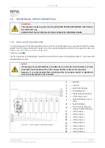
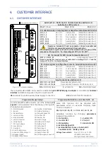
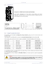
4.1.3
Programmable input free contacts
Some programmable UPS functions (indicated in
Section 4.1
), can be activated by closing an external
contact, if connected, on:
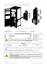
X1 / 10, 21
or
J2 / 10, 23
User Input 1 (default = Not used)
X1 / 11, 22
or
J2 / 11, 24
User Input 2 (default = Emergency GEN ON)
4.1.4
Gen Set Signaling (GEN ON)
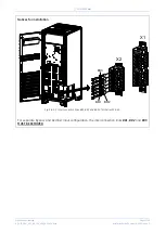
If an emergency generator set supplies the UPS in case of
Mains Failure
and the generator is
considerably unstable in frequency, it should be suitable to install the signal
“
Generator ON
”
on
X1 / 11,
22
or
J2 / 11, 24
). See
Fig. 4.1-1 / X1
and
J2.
Since the Parameter for of the reading of the Generator function is password protected, call the nearest
Service Center
for it's activation.
When this contact closes, it changes certain (programmable) functions such as:
Enabling or disabling of synchronization and consequently the
Load
transfer to generator.
Reduction or elimination or delay of
Battery
recharging during the generator operation.
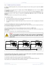
In a parallel system a separate NO (Normally Open) contact must be connected to
each individual unit.
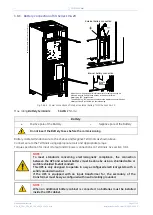
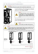
4.1.5
AUX external Maintenance Bypass
If the UPS system is equipped with an external
Maintenance Bypass Switch
, it is possible to connect a
NO
(Normally Open) voltage-free aux. contact from the
External Bypass Switch
to the programmable input
X1 / 10, 21
or
J2 / 10, 23
, making the UPS operate as if the internal switch
Q2
has closed.
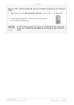
This function can be activated by changing a dedicated parameter (password required).
When this
NO
(Normally Open) contact closes, the output
Inverter Contactor
K7
it is automatically
opened and the
Load
transfer back to
Inverter
will be inhibited.
In a parallel system, the input on the customer interface of each unit must be
connected to a separate AUX contact of the External Maintenance Bypass Switch.
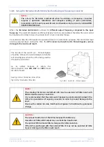
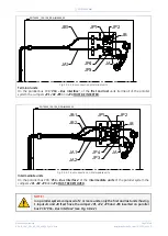
4.1.6
Auxiliary Power Supply (APS) 24 Vdc
Fig. 4.1.6-1 Terminals for connection 24Vdc
XA - 1
24Vdc
XA - 2
GND
XA - 3
24Vdc
XA - 4
GND
4
1
3
2
3
2
1
S
G
T5000_
100
-150_Custom
er i
nterfa
ce
2
4
VD
C
_
0
1
4
XA