


Critical Power
Modifications reserved
Page 39/46
GE_UPS_OPM_SGS_ISG_10K_40K_0US_V070.docx
Installation Guide
SG Series 10-20-30-40 UL S
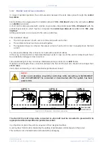
3.9.3
Control bus cable location
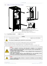
WARNING !
This operation must be performed by QUALIFIED SERVICE PERSONNEL ONLY before
the initial start-up.
ENSURE THAT THE UPS INSTALLATION IS COMPLETELY POWERED DOWN.
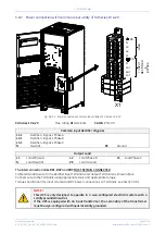
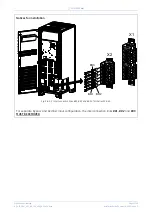
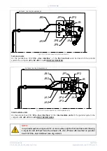
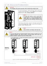
Fig. 3.9.3-1 View electronic module on intermediate unit
Access to the control bus connection.
The control bus connection between
parallel units must be made on the front
of the
electronic module
fitted behind
the front doors.
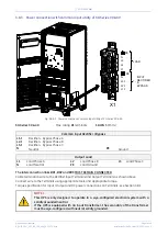
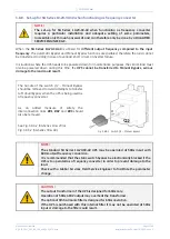
Fig. 3.9.3-2 Front view electronic module on intermediate unit
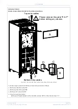
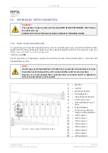
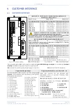
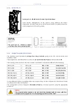
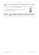
Control bus cables connection.
Plug the cables
JA
(1/2/3/4/5/6/7)
and
JB
(1/2/3/4/5/6/7)
onto the RJ
connectors
JA
and
JB
located on
parallel bus PCB
“
P34 – Bus Interface
”
(going to
“P13 – RPA Board”
J52(A)
and
J62(B)
.
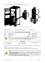
Fix both cables
JA
(1/2/3/4/5/6/7)
and
JB
(1/2/3/4/5/6/7)
to parallel bus
socket connecting the cable shield to
ground by means the cable clamps “
A
“.
SGT5000_030-040_RPA
control
b
u
s
ca
b
le
_
0
1
Q1
Q2
ON
OFF
OFF
ON
SGT50
00
_1
00
-1
50
_R
P
A
con
tr
ol
b
us
cab
le_02US
Next parallel unit
JB2
JB1
JA2
JA1
A
A
JA
JB


