


Critical Power
Modifications reserved
Page 28/46
GE_UPS_OPM_SGS_ISG_10K_40K_0US_V070.docx
Installation Guide
SG Series 10-20-30-40 UL S
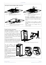
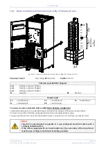
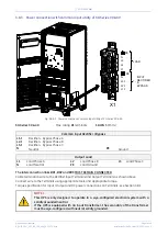
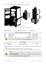
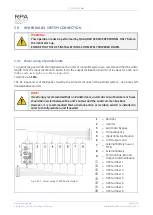
3.8.3
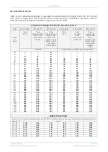
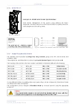
Power connection with common input utility of
SG Series 30 & 40
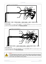
Fig. 3.8.3-1 Power connections Common Input Utility of SG Series 30 & 40
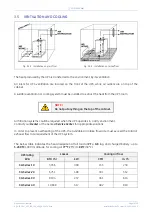
SG Series 30 & 40
Max. rating
X1
terminals:
1 AWG
(50mm
2
)
Common Input Rectifier / Bypass
L1-1
Rec Bypass Phase A
L2-1
Rec Bypass Phase B
L3-1
Rec Bypass Phase C
N
Neutral
PE
Ground
Output Load
L1
Load Phase A
L2
Load Phase B
L3
Load Phase C
N
Load Neutral
PE
Load Ground
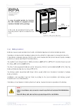
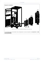
The interconnection links
BR1
,
BR2
and
BR3
MUST REMAIN CONNECTED
.
Cable terminations are to the
Rectifier Input Terminals
and
Output Terminals
as shown above.
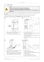
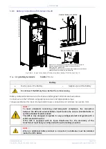
Connect wire to the
Terminals
using appropriate tools and appropriate torque.
Torque specification for
Input / Output
and
DC
power connections on
Terminals
: see Sec
tion 3.8.1
.
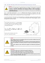
NOTE !
This UPS is only designed to operate in a wye-configured electrical system with a
solidly grounded neutral.
If the UPS is equipped with an input transformer, the secondary of the transformer
must be wye-configured with neutral solidly grounded.
L1-1
X1
RECTIFIER
1 -
INPUT
L1
LOAD
PE
PE
S
GT
50
00
_0
30
-0
40
_UP
S c
on
ne
cti
o
n co
m
m
on
_0
1U
S
L2
L3
N
L2-1
L3-1
N
OFF
ON
OFF
ON
&
BYPASS


