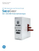
GE SecoGear, Application Manual
"With our GE SecoGear product, you can easily operate and maintain your electrical systems. Access the Application Manual through our website for a comprehensive guide on installation and troubleshooting. Download the manual for free and unleash the full potential of your SecoGear product at manualshive.com."
Share
Download


Reviews:
No comments
Related manuals for SecoGear

SE-SR2
Brand: Datalogic Pages: 16

ARCON 3G
Brand: Eaton Pages: 104

S-12741
Brand: U-Line Pages: 3

REVEX 1PH RX1 030 Series
Brand: CD Automation Pages: 65

STI-7554
Brand: STI Pages: 8

R 29 335
Brand: Dräger Pages: 92

Double EasyFit Bedguard
Brand: NRS Healthcare Pages: 4
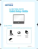
HLR4677W - 46" Rear Projection TV
Brand: Samsung Pages: 16

Tyvek 600 Plus CHA5
Brand: Dupont Pages: 20

MRM4
Brand: Woodward Pages: 460

Dual Pro Series
Brand: Sordin Pages: 22

AC-200-dual
Brand: Protec Pages: 16

Legend WL200
Brand: Harvia Pages: 4


