GE Medical Systems
Information Technologies
Responder
1000/1100 Page
8/38
Service Instructions
──────────────────────────────────────────────────────────────────
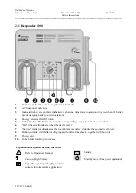
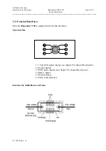
2.1 Responder 1000
1
Button to deliver the shock - together with button
8
2
AC line power indicator
3
Indicator light is green while the battery is charging (line power operation), it is red when the battery
needs charging (battery power operation)
4
Energy selector, On/Off switch
5
Indicators
2
to
360
illuminate when the corresponding energy level has been reached
6
"On" indicator illuminates when the device is On
7
"Service" indicator illuminates when a problem was detected during the automatic self-test
8
Button to initiate defibrillator charging and to deliver the shock - together with button
1
9
Power
cord
10
Tube holder for skin prep cream
Explanation of symbols used on the device
Refer to Operator's Manual
battery
Caution, High Voltage
Standby mode (line power operation)
Type CF signal input: highly insulated,
suitable for intracardiac application
227 487 20 Rev G
Summary of Contents for Responder 1000
Page 1: ...Responder 1000 1100 Version V 1 0 Servicing Instructions 227 487 20 ENG Revision G ...
Page 39: ......
Page 40: ......
Page 41: ......
Page 42: ......
Page 43: ......
Page 44: ......
Page 45: ......
Page 53: ......
Page 54: ......
Page 56: ......
Page 57: ......
Page 58: ......
Page 59: ......

