GE Medical Systems
Information Technologies
Responder 1000/1100
Page 23
/
38
Service Instruction
───────────────────────────────────────────────────────────────────
227 487 20 Rev G
8.2.2 Function Checks
AC line power LED
Connect the unit to mains. The green LED (AC line power indicator) must light up.
Power-up
Switch the unit on with energy selector switch (turn rotary switch to the first position 2J). After
power-up and during operation, the
Responder 1000/1100
runs automatic self-tests.
After power-up, the unit beeps and all LED’s will briefly light up. Afterwards the green “On-
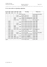
LED” lights up and the unit is ready. When the unit detects an error, the "Service" LED lights up
and an acoustic signal sounds. Every three seconds the unit try’s a new restart and test whether the
error still appears. (see chapter 6. Unit test functions)
Automatic defibrillator discharge after 60 sec
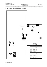
see chapter 4. Adjustment and Performance Instruction
Adjustment of charge current
see chapter 4. Adjustment and Performance Instruction
Adjustment of the charge monitor LED’s
see chapter 4. Adjustment and Performance Instruction
Adjustment of the energy
see chapter 4. Adjustment and Performance Instruction
Delivered energy
The paddles must be locked at the defibrillator-tester.
Prerequisite for the following test <energy 360 joules in 11 second>
The battery must be fully charged or the instrument must be connected to mains.
Switch instrument on. Switch energy selector to 360 joules. Start energy charge by pressing the
charge/shock key in the electrode handle. Energy must be available after approx. 11 second.
As soon as the charge operation is complete a acoustic signal sounds. Release the defibrillation
pulse with the charge/shock key and the shock key within the next 60 seconds.
Test all energy levels:
Select each energy level and start energy charge every time by pressing the charge/shock key in the
electrode handle. Check that all indicators (LED’s) light up one after the other up to the selected level.
After the device beeps (defibrillator is charged), release the Shock immediately.
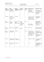
The values (tolerance range) for the energy released is given in the table next page.
If an energy adjustment proves necessary, see chapter 4. Adjustment and Performance Instruction.
Energy selected
Energy released
Summary of Contents for Responder 1000
Page 1: ...Responder 1000 1100 Version V 1 0 Servicing Instructions 227 487 20 ENG Revision G ...
Page 39: ......
Page 40: ......
Page 41: ......
Page 42: ......
Page 43: ......
Page 44: ......
Page 45: ......
Page 53: ......
Page 54: ......
Page 56: ......
Page 57: ......
Page 58: ......
Page 59: ......


