background image


9


the linkage to rise until the prop (11, view D) can slip under 

the close roller (10, view D) and hold the linkage in place. As 

the linkage moves, the output crank (12, view D) rotates the 

cross shaft (13, view D) which in turn rotates the phase bell 
cranks and compresses the two opening springs (15, view E) 

on poles 1 and 3, this closes the vacuum interrupters, and 

compresses the three wipe springs (16, view E) on each pole. 

The rotation of the cross shaft (13, view D) also changes the 

auxiliary switch (7, view D) position. The position flag on the 

front panel will then indicate “CLOSED”. After the breaker is 
closed, the charging motor is again energized and the closing 

spring is charged as described under “CLOSE SPRING 

CHARGING”. Spring charging is possible when the breaker is 

in the closed position because the linkage is held in place by 

the prop. 


5.4—Opening Operation (refer to Figure 15) 

By either energizing the trip solenoid or depressing the    

manual trip button (23, view B), the trip latch (19, view D) is 
rotated, permitting the linkage to collapse and the vacuum 

interrupter contacts to open under the force of the wipe 

springs (16, view E) and opening springs (15, view E). At the 

end of the opening stroke, the center phase wipe spring 

assembly hits a stop block on the frame that limits overtravel 
and rebound. Rotation of the cross shaft from the closed to 

the open position operates the auxiliary switch (17, view D) 

which opens the trip coil circuit. If the closing spring has been 

recharged, the linkage will be reset and the trip latch will be in 

place on the trip roller, ready for another closing operation. 


5.5—Trip-free Operation


The linkage is mechanically trip free in any location on the 

closing stroke. Electrically energizing the trip coil while closing 

will, after the auxiliary switch contacts change position, rotate 
the trip latch and permit the circuit breaker to open fully. 


The linkage will reset as in a normal open operation, and the 

closing spring will recharge as described under SPRING 
CHARGING. 


SECTION 6—Electric Control circuit 


A typical PowerVac

®

 circuit breaker ML-20 mechanism wiring 

diagram is shown in Figure 16. Check the wiring diagram 

supplied with the actual circuit breaker for its wiring. 


The close spring-charging motor circuit is established through 

the CL/MS (close latch monitor switch) switch if the close 

latch is reset the SM/LS (spring motor limit switch) if the 
closing spring is discharged and the IL/MS (Negative Interlock 

Monitoring Switch). When the closing spring is charged, the 

SM/LS interrupts the circuit. 


The close coil circuit is established through two normally 
closed 52Y relay contacts, and the latch-checking switch LCS, 

if the trip latch is reset. An auxiliary switch contact 52b is also 

in series with the close coil and closes when the breaker is 


open and opens when the breaker is closed. During a close 

operation, cam rotation closes the SM/LS contact allowing the 

52Y relay to be energized; opening its contacts in the close 
coil circuit and sealing itself in through one of its own contacts 

to the close signal. This seal-in action prevents re-closing on a 

sustained close command as the close signal must be 

removed to drop out the Y relay, and reestablish the close 

circuit, thereby providing an anti-pump feature. 


Circuit breaker mounted auxiliary switch contacts not used in 

the control circuit are bought out for control and indication 

functions. The metalclad equipment may provide a breaker 

operated stationary auxiliary switch for additional contacts 
(3, 6 or 10 stages are available). 


SECTION 7—Mechanical Checking and Slow Closing 


7.1—Visual Inspection 

Visually inspect the circuit breaker for any signs of damage or 

loose hardware. 


7.2—Closing Spring Charging 

Manually charge the breaker closing spring using the charging 

handle provided (1, Figure 4). The closing spring is charged by 

a ratcheting mechanism that advances by one ratchet tooth at 

a time. When the spring is fully charged and the spring load is 
held by the closing latch, the spring indicator (3, Figure 1) will 

change from “DISCHGD” to “CHARGED”, and a positive snap 

will be heard as the spring travels over center. 


CAUTION:  

AFTER THE SPRING IS COMPLETELY 

CHARGED, AS INDICATED IN FIGURE 4, FURTHER FORCING 

CHARGING HANDLE MAY CAUSE DAMAGE TO THE 
CLOSING LATCH AND ITS ASSOCIATED PARTS. 


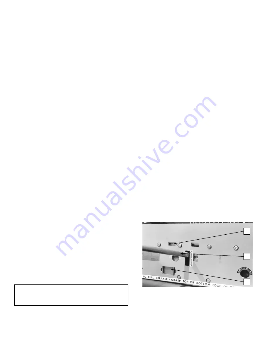
Figure 4   Manual charging 


1.  Manual charging handle 


2.  Close spring gag hole 


     (shown in closed position) 


3.  Spring charge indication 

 3 

 1 

 2 

Summary of Contents for PowerVac

Page 1: ...DEH 40368 Instructions g PowerVac Vacuum Circuit Breaker with ML 20 Mechanism ...

Page 2: ...ment 12 Description Page SECTION 9 Electrical Checks 14 9 1 Electrical Operation 14 9 2 High Potential Test 14 9 2 1 Primary Circuit 14 9 2 2 Secondary Circuit 14 9 3 Primary Circuit Resistance 14 9 4 Vacuum Interrupter Integrity Test 14 9 5 Insulation Test 15 SECTION 10 Checking and Installing Breakers 16 SECTION 11 Maintenance 17 11 1 General 17 11 1 1 PowerVac Interrupter 17 11 1 2 Trouble Repo...

Page 3: ... Toggle linkage positions of the ML 18 mechanism 25 15 Schematic of ML 18 mechanism 27 16 Typical wiring diagram for ML 18 mechanism 29 17 PowerVac breaker left front view 30 18 PowerVac breaker right rear view 30 19 Trip coil and linkage 31 20 Close coil linkage 32 21 Bottom view of the ML 18 mechanism 33 22 Negative interlock 34 23 Wipe spring compression 34 Table Page 1 Control Device and Volta...

Page 4: ...tices such as OSHA publications National Electric Safety Code ANSI C2 National Electric Code and National Fire Protection Association NFPA 70B Electrical Equipment Maintenance must be closely studied and followed During actual work supervision should audit practices to assure conformance 1 2 Maintenance Excellent maintenance is essential for reliability and safety of any electrical equipment Maint...

Page 5: ...nts of each shipping package are listed on the Master Packing List In addition this list includes the number of the shipping crate in which miscellaneous parts needed to install and operate equipment such as hardware contact lubricant touch up paint breaker closing devices etc are located Normally such devices are packed in a cardboard carton B Inspecting for Damage All equipment leaving the facto...

Page 6: ... close button then the manual trip button The indicator flags on the front of the breaker should show OPEN and DISCHGD All mechanical and electrical checks should be completed before putting breakers in service 4 2 Interlocks Each PowerVac vacuum circuit breaker is provided with the following interlocks 4 2 1 Rating Interference Plate This interlock 1 Figure 2 permits only a breaker with a matchin...

Page 7: ...linkage connected to the cross shaft extends a détente angle 3 Figure 17 out through the left side of the mechanism frame when the breaker contacts are in the closed position If the breaker is in the CONNECT or DISCONNECT TEST position in the metalclad the détente angle locks into the racking mechanism to prevent access to the hex section of the racking screw 4 2 5 Closing Spring Gag Interlock The...

Page 8: ... view C mounted within the charging arms oscillates with the charging arms Starting from its rear most position as the charging arms rotate forward a spring forces engagement of the driving pawl with a tooth of the ratchet wheel The ratchet wheel is advanced by the rotating charging arms and pawl assembly Advancement of one tooth spacing is provided for each oscillation of the system The ratchet m...

Page 9: ... in Figure 16 Check the wiring diagram supplied with the actual circuit breaker for its wiring The close spring charging motor circuit is established through the CL MS close latch monitor switch switch if the close latch is reset the SM LS spring motor limit switch if the closing spring is discharged and the IL MS Negative Interlock Monitoring Switch When the closing spring is charged the SM LS in...

Page 10: ...osing To manually slow close the breaker contacts install the closing spring gag as described above and push the manual close button 11 Figure 3 Then put the manual charge handle on the manual charge lever and move the handle up and down The breaker will be fully closed when the spring charge indicator shows CHARGED CAUTION WITH THE GAG PLATE INSTALLED THE BREAKER CLOSED AND OPENING SPRINGS CHARGE...

Page 11: ... shown in Figure 7 Using a reference block make a mark on the tape near the top on all three poles It is also advisable to put a reference mark on the tape to identify to which pole the tape is applied Remove the closing spring gag plate and close the breaker Using the same procedure as above re mark the tape This new mark will be near the bottom of the tape Trip the breaker remove the tapes and r...

Page 12: ...er the full plunger travel To check the trip coil plunger gap adjustment the breaker is to be closed with the closing spring discharged Dimension T between the plunger button and the coil housing should be between 0 20 and 0 25 inch This dimension is obtained when the trip plunger button is depressed until resistance is felt If the breaker is equipped with an optional second trip coil use same pro...

Page 13: ...13 Figure 10 Control switches LCS Switch ...

Page 14: ...uit Remove the wire connecting the secondary disconnect pins and reconnect the motor leads 9 3 Primary Circuit Resistance A resistance check of the primary circuit may be made with the breaker closed Use a low resistance measuring instrument rated 100 amperes which measures in microhms The 100 ampere reading should be 25 or less microhms for a 600 1200 or 2000 amp Breaker when connected across the...

Page 15: ...MAL X RADIATION WILL BE PRODUCED Although a AC hi potential test is recommended for checking the vacuum integrity a DC hi potential test can also be conducted on the vacuum interrupters at 50 kV and held for 10 seconds with the restrictions noted as follows No attempt should be made to try to compare the condition of one vacuum interrupter with another nor to correlate the condition of any interru...

Page 16: ...HE BREAKER WILL NOT CLOSE ELECTRICALLY RECHECK THE 52 LCS ADJUSTMENT IF CONTROL POWER IS NOT AVAIL ABLE PUSH THE MANUAL CLOSE BUTTON AND RECHARGE THE CLOSING SPRING MANUALLY SPRING CHARGING WILL OCCUR AUTOMATICALLY IF CONTROL POWER IS CONNECTED With the breaker in the CLOSED condition attempt to install the racking crank The racking crank should be blocked by the POSITIVE INTERLOCK Trip the breake...

Page 17: ... no load or 200 normal load switching operations Mild service conditions are defined as an environment in which the switchgear is protected from the deleterious effects of conditions such as Salt spray Changes in temperature that produce condensation Conductive and or abrasive dust Damaging chemicals and fumes Vibration or mechanical shock High relative humidity 90 Temperature extremes below 30 C ...

Page 18: ... a visual inspection of the breaker Check for loose or damaged parts 2 Perform slow closing operation described under MECHANICAL CHECKING AND SLOW CLOSING 3 Check the erosion indicator and the wipe and gap as described under DIMENSIONAL CHECKS 4 Perform the vacuum interrupter integrity test as described under ELECTRICAL CHECKS 5 Lubricate the breaker operating mechanism as described under LUBRICAT...

Page 19: ... six volts DC and one ampere through the vacuum interrupter contact to indicate closed or open condition Typical time ranges vary with coil voltage but nominal values are Initiation of trip signal to contact parting 5 Cycle Breaker 32 45Milliseconds 2 Milliseconds Maximum Pole Spread Initiation of close signal to contact closing 45 75 Milliseconds DC Control Voltage 35 65 Milliseconds AC Control V...

Page 20: ...g assemblies A change in opening speed affects the closing speed Reference Figure 12 The operating speeds for a 5 cycle breaker are as follows Operation Operation Operation Operation Feet Per Second Feet Per Second Feet Per Second Feet Per Second Open 4 3 5 6 Close 2 6 3 9 V I STOP CENTER PHASE Figure 12 Contact gap adjustment ...

Page 21: ...nuity indicator on c Advance operating rod two and one half 2 1 2 additional turns d Tighten lock nut to 40 50 pounds foot and the coupling clamp capscrews to 8 10 pounds foot e Check contact wipe must be 0 160 0 185 inch set all three phases before measuring It is not necessary that all three poles have the same wipe measurement as long as all three poles fall within the specified limits f Check ...

Page 22: ...itch Replacement With the breaker open and the closing spring discharged remove retaining clip from auxiliary switch shaft Observe and make of the direction of the index mark on the end of the shaft and the position of the operating link in relation to the stop screw Remove mounting hardware securing auxiliary switch to mechanism plate Slide auxiliary switch and shaft out of operating link Before ...

Page 23: ...ch wrench Refer to 4 Figure 6 Adjust by rotating the operating rod insulator The thread is 1 2 13 and each turn will give about 0 076 inch change in primary wipe Screw the operating rod insulator toward the interrupter to increase wipe 4 After setting the contact wipe on each phase torque the operating rod locknut 4 Figure 6 to 40 50 pounds foot while holding the hex projection 6 to prevent the op...

Page 24: ...ANCE ITEM Figure 13 Spring Discharge Interlock The breaker should be open with the closing spring charged 1 Back off 1 4 inch linkage adjusting screw 2 While holding roller at 0 995 inch dimension advance adjusting screw to just touch interlock lever 3 Check that spring discharges with roller at 0 561 inch minimum dimension 4 Close latch must reset as indicated 16 7 Negative Interlock THIS INTERLO...

Page 25: ...d on next page A Breaker open spring discharged 1 Output crank 2 Jackshaft 3 Trip latch 4 Trip roller 5 Closing roller 6 Trip link 7a Closing toggle 7b Closing toggle 8 Prop 9 Closing cam 10 Prop spring 11 Linkage return spring NOTE Shading indicates fixed pivots B Breaker open spring charged ...

Page 26: ...26 Figure 14 Continued C Breaker closed spring discharged D Breaker closed spring charged ...

Page 27: ... 14 Bell cranks 4 Charging arms 15 Opening springs 5 Ratchet wheel 16 Wipe springs 6 Driving pawl 17 Auxiliary switch 7 One way clutch 18 Trip solenoid 8 Close latch 19 Trip latch 9 Close cam 20 Over travel stop 10 Close roller 21 Latch check switch 11 Prop 22 Gear motor 23 Manual trip button Continued on next page ...

Page 28: ...28 Figure 15 Continued Partial View A Partial View B Partial View C Partial View D Partial View D ...

Page 29: ...29 Figure 16 Typical wiring diagram for ML 20 mechanism ...

Page 30: ...ngle 2 Track rollers 3 Positive interlock bar 4 Closing spring discharge roller 5 Negative interlock roller 6 Rating interference plate 7 Front cover 8 Racking engagement lever 9 Secondary coupler Figure 18 PowerVac breaker right rear view 7 8 2 4 9 6 8 7 8 2 3 5 1 ...

Page 31: ...31 Figure 19 Trip coil and linkage 1 Trip coil 2 Closing spring 3 Trip linkage adjusting rod and nut 3 1 2 ...

Page 32: ...32 Figure 20 Close coil linkage 1 Close linkage adjusting nut 2 Close linkage adjusting rod 3 Link to close latch actuator 1 2 3 ...

Page 33: ...SM LS motor control switch 4 Spring charging motor 13 LCS latch checking switch 5 Trip coil 14 CL MS close latch monitor switch 6 Close coil 15 Stationary auxiliary switch operator 7 Ratchet wheel 16 Close latch adjustment screw 8 Closing cam on 0 1 2 breakers only 9 52Y relay 17 Close linkage pivot 3 4 6 1 11 10 9 2 12 8 16 13 2 17 7 15 ...

Page 34: ...er making contact with adjusted trip coil rod CAUTION This is a safety feature not a routine maintenance item Figure 22 Negative interlock A change in the setting of the close latch stop bolt will affect the adjustment of the spring discharge interlock Figure 23 Spring wipe 34 ...

Page 35: ...E SEE SECTION 8 6 12 TIMING SEE SECTION 12 19 CONTACT SPEEDS SEE SECTION 13 20 TABLE 3 ADJUSTMENTS ITEM BREAKER CL SPRING OP SPRING MEASUREMENT PG CONTACT WIPE CLOSED CHARGED CHARGED ADJUST OPERATING ROD TO OBTAIN REQUIRED DIMENSION 23 CONTACT GAP OPEN DISCHARGED DISCHARGED ADVANCE OR RETARD GAP ADJUSTING NUTS TO SET GAP 23 CONTACT EROSION CLOSED DISCHARGED CHARGED ALIGN REFERENCE TAB WITH BAND ON...

Page 36: ...rupter 17 Primary Insulation Parts 17 Service Conditions 17 Transfer Finger Wear 17 Measurements Table 2 35 Mechanical Adjustments Close Coil Plunger 24 Close Latch Stop Bolt 24 Contact Gap 23 Negative Interlock 24 Spring Discharge Interlock 24 Trip Coil Plunger 24 Wipe Adjustment 23 Mechanical Checking and Slow Closing 9 10 Mechanism 17 21 33 Motor Replacement 22 N Negative Interlock 24 34 Negati...

Page 37: ...tion to Ground Internal Insulation to Ground Insulating Medium Isolating Contact Bushing Interrupter Seals Gaskets Air System SF6 System C T Resistor Sw or Aux Int Voltage Grading Device Line Terminals Compressor Heater Electrical Controls Wiring Operating Mechanism Mechanical Linkage Other _______________________________________________ ____________________________________________________________...

Page 38: ... during and after failure 4 Oscillograms attach with explanation interpretation 5 Attach a description of the exact position of all mechanical components from the control solenoid through all interrupter contacts as applicable photograph each in detail before mechanisms are moved supply copies of photos with report 6 Describe arc damage and location of arc products relative to valve seals photogra...

Page 39: ...Intentionally Left Blank ...

Page 40: ...nance Should further information be desired or should particular problems arise which are not covered sufficiently for the purchaser s purposes the matter should be referred to the General Electric Company g GE Electrical Distribution Control General Electric Company Switchgear Business Department 510 East Agency Road West Burlington Iowa 52655 DEH 40368 1100 2000 General Electric Company ...

Reviews: