background image

Chapter 4. Using Special Features

64

Model PM880 Portable Hygrometer User’s Manual

4.8.3b Entering a Label for the Table

1.

The Table box should be highlighted. Press 

[ENTER]

 to open the 

drop-down menu.

2.

Use the arrow keys to scroll to the desired table number and press 

[ENTER]

.

3.

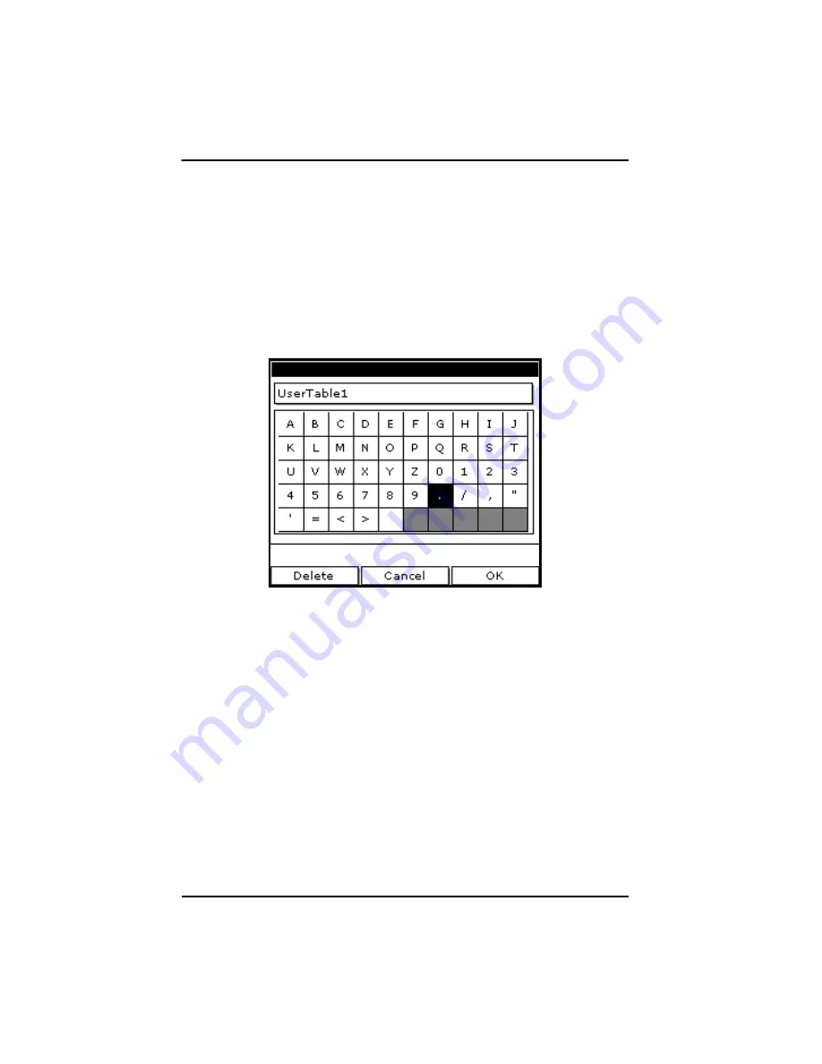
Use the arrow keys to move to the Table ID box and press 

[ENTER]

. A 

screen similar to Figure 28 appears.

Figure 28: Text Creation Window

4.

Use the arrow keys to scroll to the desired character and press 

[ENTER]

Press 

[F1]

 (

Delete

) to delete any unwanted letters or numbers. Press 

[SEL]

 to view the three screens with the available characters and 

symbols for creating a label for the table.

5.

Repeat this procedure until you have created the desired label for the 
table of up to thirty-two characters. 

6.

When you have finished, press 

[F3]

 (

OK)

.

Note:

It is not necessary to enter the “#Data Points” or “Max Points” text 
boxes. The meter automatically enters this data.

Summary of Contents for PM880

Page 1: ...GE Measurement Control Solutions Moisture 910 247 Rev F May 2011 Model PM880 Portable Hygrometer User s Manual ...

Page 2: ......

Page 3: ...cs com 2011 General Electric Company All rights reserved Technical content subject to change without notice GE Measurement Control Solutions Model PM880 Portable Hygrometer User s Manual 910 247 Rev F May 2011 ...

Page 4: ...ii no content intended for this page ...

Page 5: ...ion is also included when applicable Safety Issues WARNING It is the responsibility of the user to make sure all local county state and national codes regulations rules and laws related to safety and safe operating conditions are met for each installation Auxiliary Equipment Local Safety Standards The user must make sure that he operates all auxiliary equipment in accordance with local codes stand...

Page 6: ...ic Equipment WEEE take back initiative directive 2002 96 EC The equipment that you bought has required the extraction and use of natural resources for its production It may contain hazardous substances that could impact health and the environment In order to avoid the dissemination of those substances in our environment and to diminish the pressure on the natural resources we encourage you to use ...

Page 7: ... 5 Displaying Measurements 15 1 5 1 Selecting the Number of Measurements 15 1 5 2 Selecting the Types of Measurements 16 1 6 Saving Data in a Site File 17 1 6 1 Accessing the Site Manager 17 1 6 2 Entering a Site Name 17 Chapter 2 Taking Measurements 2 1 Installing the Probe in a Sample System 21 2 1 1 Installing a Moisture Probe 22 2 2 Connecting the Sample System to the Process 23 2 3 Making Pro...

Page 8: ...rements 33 3 2 3 Selecting Numeric Line or Bar Graph Format 34 3 2 4 Setting Up the Numeric Format 34 3 2 5 Adjusting the Line Bar Graph Scale 36 3 3 Creating Function Key Shortcuts 37 3 3 1 Assigning Re assigning a Function Key 38 3 3 2 Clearing a Function Key 39 3 4 Using the Backlight 39 3 4 1 Turning the Backlight On and Off Manually 39 3 4 2 Setting the Backlight Timer 40 3 5 Adjusting the Co...

Page 9: ...age 49 4 5 Setting a Probe Calibration Reminder 50 4 5 1 Accessing the Probe ID Tab 50 4 5 1 Entering Probe Information 51 4 6 Using Automatic Calibration AutoCal 52 4 7 Entering Constants and User Functions 54 4 8 Entering a User Constant 55 4 8 1 Entering a Saturation Constant 56 4 8 2 Entering User Functions 58 4 8 3 Setting Up User Tables 62 4 9 Using Computer Enhanced Response 66 4 9 1 Respon...

Page 10: ...Log 83 5 4 Ending a Log 84 5 5 Viewing All Logs 85 5 6 Viewing Log Setup Details 86 5 7 Displaying Logged Data 88 5 7 1 Using the Graph Format 88 5 7 2 Using the Spreadsheet Format 92 Chapter 6 Managing Files 6 1 Saving a New Site File 96 6 2 Recalling a Site File 98 6 3 Saving a Site File 99 6 4 Renaming a Site or Log File 100 6 4 1 Renaming a Site File 100 6 4 2 Renaming a Log File 102 6 5 Copyi...

Page 11: ...ng Panaview 117 7 2 Transferring and Printing Files Key 119 7 3 Printing a Site or Log File 119 7 3 1 Printing a Site File 120 7 3 2 Printing a Log File 121 7 4 Printing Reports 123 7 5 Transferring a File To a PC 124 7 6 Transferring a File from a PC 127 7 6 1 Using Windows Explorer in Windows 95 98 2000 127 7 6 2 Using Windows NT 4 0 128 7 6 3 Using Windows 95 98 129 7 6 4 Using Windows 2000 129...

Page 12: ...Changing Security Settings 139 8 7 1 Setting the Security Passcodes 140 8 7 2 Setting Remote Access Security 141 8 8 Updating PM880 Software 143 8 8 1 Upgrading Requirements 143 8 8 2 Updating Software Using IrOBEX 145 8 8 3 Updating Software Using IrCOMM 147 8 9 Removing Replacing the Batteries 150 8 10Recharging the Batteries 151 8 10 1 Removing the Battery Pack 151 8 10 2 Configuring the Batter...

Page 13: ... 9 3 Cabling 168 9 4 Overall 168 9 5 Operational 169 9 6 Electronics 170 9 7 Moisture Measurement 172 9 8 Dew frost Point Temperature 172 9 9 Temperature Measurement 173 9 10Pressure Measurement 173 9 11Sample System 174 9 12Optional Accessories 174 Appendix A Measurement Considerations A 1 Choosing a Measurement Site 175 A 2 Moisture Temperature Probe Considerations 176 A 3 Sample System Guidelin...

Page 14: ...Contents xii Model PM880 Portable Hygrometer User s Manual no content intended for this page ...

Page 15: ... charging and minimal setup to begin taking measurements This chapter is designed to provide a step by step guide to getting the meter up and running as quickly as possible Additional programming options are discussed in later chapters Follow the sections in this chapter to setup your meter This chapter includes the following information Charging the Battery Pack Powering On and Off Entering Data ...

Page 16: ...inuous operation depending on the probe type and the PM880 usage An internal battery gauge indicates the remaining power in the pack Before charging the battery pack make sure the charger is properly configured Use the instructions below 1 1 1 Removing the Battery Pack 1 Make sure you are in a general purpose location where you can safely charge the pack WARNING THE BATTERY PACK CAN BE INSTALLED A...

Page 17: ...causing injury and or damage IMPORTANT SAFETY INSTRUCTIONS SAVE THESE INSTRUCTIONS DANGER TO REDUCE THE RISK OF FIRE OR ELECTRICAL SHOCK CAREFULLY FOLLOW THE GUIDELINES BELOW BE SURE THE VOLTAGE SELECTOR IS IN THE CORRECT VOLTAGE POSITION BEFORE PLUGGING IT IN SEE THE BOTTOM OF THE CHARGER FOR USE IN THE UNITED STATES THE VOLTAGE SELECTOR SWITCH MUST BE PLACED IN THE 115 VOLT POSITION FOR USE IN C...

Page 18: ...ED glows and the charger automatically begins charging the pack Note The pack is fully charged when the amber LED goes out approximately 4 5 hours IMPORTANT When you receive your unit you should completely charge the battery pack before using it for the first time 3 Remove the pack from the charger and reinstall it in the PM880 Refer to Checking the Battery Status on page 133 for details on monito...

Page 19: ... turn the PM880 on press the red button in the upper right hand corner of the keypad Immediately upon powerup the PM880 displays a series of messages and performs various checks The screen then appears similar to the one shown in Figure 1 Note If the meter displays a Probe Reminder message press ENTER Figure 1 Screen After Powering On Note If the meter fails any of these tests contact the factory ...

Page 20: ...ed 6 Model PM880 Portable Hygrometer User s Manual 1 2 2 Powering Off 1 To turn the PM880 off press the red key for 3 seconds The screen now appears similar to Figure 2 2 Press F1 to shut down the PM880 Figure 2 Shutdown Menu ...

Page 21: ...nd return to Operate Mode without changing data Note If you enter an incorrect numeric value press the key to erase the last digit entered 1 4 Entering Setup Data For immediate operation the PM880 requires only a moisture probe and its corresponding calibration data You should enter data for each site where you plan to make a measurement Once entered you can save it into a file that can be recalle...

Page 22: ...u map Note You may also enter a constant value rather than a live input for moisture temperature or pressure measurement For more information refer to Entering Constants and User Functions on page 54 1 If the menu is not active press MENU 2 Use the arrow key to scroll to Program and press ENTER 3 Use the arrow key to scroll to Probe and press ENTER The screen appears similar to Figure 3 Figure 3 P...

Page 23: ...l to the desired selection and press ENTER 6 Press F3 OK to exit Next do one of the following If you are using an M or TF Series probe proceed to Entering Calibration Data on the next page If you are using an MIS or an MISP2 Probe proceed to Displaying Measurements on page 15 Note If you have an MIS probe that was sent back to the factory for calibration without the electronics module you need to ...

Page 24: ...ch Calibration Data Sheet consists of a list of data points that you will need to enter or verify and lists its corresponding probe serial number Calibration Data Sheets are usually packed inside the probe cases Since the PM880 enables you to use more than one probe the meter provides a place to enter the probe serial number to help you match the probes to the corresponding site files The probe se...

Page 25: ... Probe ID tab and press ENTER A screen similar to Figure 4 appears Figure 4 Probe ID Window 5 Use the arrow keys to scroll to S N and press ENTER 6 Use the numeric keys to enter the serial number from the Calibration Data Sheet and press ENTER The serial number also appears on the hex nut of the moisture probe 7 Use the arrow keys to scroll to the suffix box and press ENTER to open the drop down l...

Page 26: ...t is not necessary to enter calibration data for the MISP2 probe Enter moisture calibration data MH or FH and dewpoint readings up to 20 data points for the moisture probe as described below Refer to Figure 9 on page 19 for a menu map Note If you are using an MIS probe and do not need to enter data proceed to Displaying Measurements on page 15 1 If the menu is not active press MENU 2 Use the arrow...

Page 27: ...ys to scroll to additional data points and repeat steps 5 6 and 7 until you have entered the values for each data point Note To insert an additional data point press F1 Insert To delete a data point press F2 Delete 9 When you have completed entering values press F3 EXIT Next do one of the following If the probe has a pressure transducer proceed to step 3 in Entering Pressure Calibration Data on pa...

Page 28: ...t active press MENU 2 Use the arrow key to scroll to Program and press ENTER 3 Use the arrow key to scroll to Calibrate and press ENTER 4 Use the arrow key to scroll to Pressure and press ENTER The screen appears similar to Figure 6 Note The corresponding mV value can be in psig English or kPa metric The supplied Calibration Data Sheets list these values in psig If you want to change the system un...

Page 29: ...ou have completed entering values press F3 Exit 10 Press F3 OK and proceed to Displaying Measurements 1 5 Displaying Measurements The PM880 can display one to four measurement parameters simultaneously There are two parts for displaying measurements selecting the number of measurements and then selecting the type of measurements See Figure 9 on page 19 for a menu map 1 5 1 Selecting the Number of ...

Page 30: ...ER The screen appears similar to Figure 7 The left column displays the five measurement types and the right column displays the measurement units Figure 7 Select Measurement Window 3 Use the arrow keys to scroll to the desired measurement type and press SEL 4 Use the arrow keys to select the desired measurement unit or diagnostic parameter Note Press F3 No Unit to display a measurement with no uni...

Page 31: ...a you have entered into a file see Figure 9 on page 19 for a menu map 1 6 1 Accessing the Site Manager 1 If the menu is not active press MENU 2 Use the arrow key to scroll to Site and press ENTER 3 Use the arrow key to scroll to Site Manager and press ENTER 4 Press MENU 5 Use the arrow key to scroll to File and press ENTER 1 6 2 Entering a Site Name 1 Use the arrow keys to scroll to New and press ...

Page 32: ...wing Press F2 No if you do not need to use a template or Press F3 Yes if you do want to use it as a template Note If you are saving a new file as a template the PM880 will ask if you want to Save Current Site press F2 No or F3 Yes 6 Press F3 Exit 7 Press MENU The new site name is displayed in the upper left corner of the screen You have completed entering site data Next do one of the following If ...

Page 33: ... the entries and return to Menu Press F3 OK to confirm the entries and return to Menu Site Manager Save 1 View 2 Views 3 Views 4 Views New Name File Probe M2 M2T TF MISP None Hygro Constant Temperature Constant Pressure Constant Calibrate Pressure Hygro MH FH Dew Point Zero FP Zero kPa Span FP Span kPa Program Menu Probe ID S N ...

Page 34: ...Model PM880 Portable Hygrometer User s Manual 20 Chapter 1 Getting Started no content intended for this page ...

Page 35: ... for more information on selecting measurement sites and sample system construction Installing the Probe in a Sample System Connecting the Sample System to the Process Connecting the Probe to the Electronics Recalling a Site File Operating the Sample System Conducting a Leak Test Shutting Down the Sample System 2 1 Installing the Probe in a Sample System Moisture probes are installed into a portab...

Page 36: ...ead it see Figure 10 Install moisture probes with different fittings in the appropriate manner Note Standard moisture probes have a sintered stainless steel shield that protects the aluminum oxide sensor Leave the shield in place for maximum protection Figure 10 Probe Fitting Location 2 Hand tighten the probe in a clockwise direction then tighten it an additional 1 8 turn with a wrench ...

Page 37: ...Close the pipeline sample tap valve 3 Remove the sample system from its case 4 Be sure the sample system inlet needle valve is closed and the filter coalescer outlet needle valve and sample outlet needle valve are open 5 Connect the sample system to the sample tap We recommend using 1 4 stainless steel tubing The distance from the sample tap to the sample system should be a short as possible typic...

Page 38: ...e connector before the cable may be properly inserted into the probe and secured 3 Connect the other end of the probe cable to the top of the unit by aligning the red dot on the cable connector at the 12 o clock position See Figure 12 for the connector location Note Remove the probe cable by pulling back the spring loaded sleeve and pulling the cable out of the connector Figure 12 Connection Locat...

Page 39: ...not active press MENU 2 Use the arrow key to scroll to Site and press ENTER 3 Use the arrow key to scroll to Site Manager and press ENTER 2 4 2 Retrieving the Site File 1 Use the arrow key to scroll to the desired site and press MENU 2 Use the arrow key to scroll to File and press ENTER 3 Use the arrow key to scroll to Open and press ENTER 4 The PM880 asks you to confirm press F3 Yes 5 Press F3 Ex...

Page 40: ...pressure 3 Begin closing the filter coalescer outlet needle valve and the sample outlet valve until both valves are nearly closed 4 Adjust the sample outlet needle valve and the filter coalescer outlet valve until you feel a slight pressure against your finger at the venting tubes 5 Open the inlet valve fully Be sure the flow out of the venting tubes remains the same as in step 4 To prevent physic...

Page 41: ...dle valve 2 Slowly open the filter coalescer outlet needle valve several turns to blow out any contaminants that may have accumulated in the coalescer valve or venting tube 3 Slowly close the sample inlet valve and allow the sample system to depressurize at a rate of approximately 10 psig per second 4 Close the sample tap valve permanently mounted on the pipeline 5 Crack the inlet needle valve to ...

Page 42: ...Chapter 2 Taking Measurements 28 Model PM880 Portable Hygrometer User s Manual no content intended for this page ...

Page 43: ...ons that follow to setup and make adjustments to the PM880 screen This chapter discusses the following Screen Components page 30 Setting Up the Screen to Display Measurements page 32 Creating Function Key Shortcuts page 37 Using the Backlight page 39 Adjusting the Contrast page 41 Taking a Bitmap Screen Capture Snapshot page 42 ...

Page 44: ...e middle of the screen is the work area that displays measurements numerically or as bar or line graphs During programming the work area displays menu prompts The bottom of the screen displays error messages see Error and Screen Messages on page 154 for more details the system tray and the function keys The system tray displays icons that indicate meter operations not otherwise shown see Table 1 o...

Page 45: ...data transfer in progress Alert Indicates the meter encountered an error in operation Log Indicates a log is pending no marks or running marks Backlight Indicates that backlight has been activated Low Battery Alert Indicates 10 minutes or less of battery run time Snapshot To file Indicates that the Snapshot function has been activated so users can take screen captures To Printer ...

Page 46: ...consists of the following Selecting the Number of Views Measurements page 32 Selecting the Types of Measurements page 33 Selecting Numeric Line or Bar Graph Format page 34 Setting Up the Numeric Format page 34 Adjusting the Line Bar Graph Scale page 36 Use the section s that follow to set up the PM880 screen 3 2 1 Selecting the Number of Views Measurements 1 If the menu is not active press MENU 2 ...

Page 47: ...he screen appears similar to Figure 15 The left column displays the five measurement types and the right column displays the measurement units 3 Use the arrow keys to scroll to the desired measurement type and press SEL 4 Use the arrow keys to select the desired measurement unit or diagnostic parameter Note Press F3 No Unit to display a measurement with no units 5 Press F3 OK 6 Repeat this section...

Page 48: ...at and press ENTER The PM880 displays the desired format and returns to taking measurements 3 2 4 Setting Up the Numeric Format 1 Press SEL to move the pointer to the window you want to change and press ENTER 2 Use the arrow keys to scroll to Format and press ENTER The screen appears similar to Figure 16 Note If FORMAT does not appear in the menu move to a window that is not displaying a line or b...

Page 49: ...rom the following Default displays the factory default number of decimal digits for the selected measurement Fixed Decimal specifies how many digits are to the right of the decimal Scientific format displays the value in mantissa exponent format expressed to the power of 10 5 Repeat steps 3 and 4 for Decimal Places or proceed to the next step to exit You can select from 0 to 4 places 6 Press F3 OK...

Page 50: ...ress ENTER 2 Use the arrow keys to scroll to Limits and press ENTER A screen similar to Figure 17 appears Figure 17 Line Graph Parameters Window 3 Use the arrow keys to scroll to Minimum and press ENTER 4 Use the numeric keys to enter the minimum value for the graph and press ENTER 5 Repeat steps 3 and 4 for the maximum value 6 Do one of the following If you are using a line graph proceed to step ...

Page 51: ...ll to the desired entry and press ENTER An X in the box activates the option Choose from the following Use lines connect points on graph with lines Plot average value not currently available Show minimum and maximum not currently available 10 Press F3 OK The PM880 displays the new format and returns to taking measurements 3 3 Creating Function Key Shortcuts The three function keys at the bottom of...

Page 52: ...to FKeys and press ENTER 4 Use the arrow keys to scroll to the desired key and press ENTER 5 Use the arrow keys to scroll to the desired function from the displayed list 6 Press F3 YES The PM880 returns to taking measurements The newly assigned function appears above the assigned function key 3 3 1b Method 2 Using the Program Menus 1 Use the keypad to go to the function that you want to assign to ...

Page 53: ...at helps in viewing data Since the backlight uses more energy the PM880 has a backlight timer that can be set to automatically turn the backlight off after a specified time in order to conserve battery life The PM880 also enables you to turn the backlight on and off manually Use the sections that follow to operate the backlight 3 4 1 Turning the Backlight On and Off Manually To manually turn the b...

Page 54: ...row key to scroll to Meter and press ENTER 3 Use the arrow key to scroll to Backlight and press ENTER 4 Use the arrow key to scroll to Backlight Off and press ENTER 5 Use the numeric keys to enter the number of minutes that the backlight remains on from 0 to 60 6 Press ENTER to confirm the entry 7 When you are done press F3 OK The PM880 returns to taking measurements ...

Page 55: ...se the arrow key to scroll to Meter and press ENTER 3 Use the arrow key to scroll to Contrast and press ENTER A screen similar to Figure 18 appears Figure 18 Display Options Window 4 Use the arrow keys to scroll to Darker or Lighter 5 Press the ENTER button repeatedly until the screen has the desired contrast 6 When you are done press F3 OK The PM880 returns to taking measurements ...

Page 56: ... desired selection and press ENTER You can choose from the following Off to turn the snapshot feature off To Printer to send the snapshot to the printer To File to send the snapshot to a file Note In order to send a screen capture to a printer the PM880 must be properly configured to IR transfer Refer to Setting Up the PM880 IR Communications on page 110 An icon of a printer or camera appears on t...

Page 57: ...nter and then transmits the file Note If the sensor cannot locate a printer a window appears indicating that it cannot find a device If it locates more than one compatible infrared device within its range it asks you to select the desired device To File the captured file appears as ScreenXX bmp in the Drive Manager To transfer the file to a PC follow the instructions in Transferring a File to a PC...

Page 58: ...Chapter 3 Using the PM880 Screen 44 Model PM880 Portable Hygrometer User s Manual no content intended for this page ...

Page 59: ...intenance and Troubleshooting Selecting English or Metric Units page 46 Entering Date and Time page 46 Changing the Date and Time Appearance page 47 Adding a Message to a Site File page 49 Setting a Probe Calibration Reminder page 50 Using Automatic Calibration page 52 Entering Constants and User Functions page 54 Using Computer Enhanced Response page 66 Entering Reference Data page 70 Using the S...

Page 60: ...easurements 4 2 Entering Date and Time The PM880 displays the current date and time above the measurements in the upper right corner of the screen The Date Time command enables you to set the date or time The current date and time are required for correct data logging operation 1 If the menu is not active press MENU 2 Use the arrow key to scroll to Meter and press ENTER 3 Use the arrow key to scro...

Page 61: ...o suit local preferences You can select from various date formats and a time display of AM PM or 24 hour time Use the following steps to alter the date and time display 4 3 1 Accessing the Locale Tab 1 If the menu is not active press MENU 2 Use the arrow key to scroll to Meter and press ENTER 3 Use the arrow key to scroll to Locale and press ENTER A screen similar to Figure 19 appears Figure 19 Lo...

Page 62: ...row keys to scroll to the desired separator and press ENTER 3 Repeat steps 1 and 2 for the other separators 4 3 2 Selecting the Date Time Format 1 Use the arrow keys to scroll to Date Format and press ENTER 2 Use the arrow keys to scroll to the desired format and press ENTER 3 Repeat steps 1 and 2 for the time format 4 Press F3 OK and then press MENU The PM880 returns to taking measurements The ne...

Page 63: ...se the arrow key to scroll to the desired site Note The list of site files in the Site Manager can be listed chronologically or alphabetically Refer to Sorting Files in the Site Drive Log Manager on page 108 2 Press MENU 3 Use the arrow key to scroll to Site and press ENTER 4 Use the arrow key to scroll to Message and press ENTER 4 4 3 Entering a Site Message 1 Press F1 Delete to delete any unwant...

Page 64: ...ion dates and a calibration reminder Use the following steps to enter probe data 4 5 1 Accessing the Probe ID Tab 1 If the menu is not active press MENU 2 Use the arrow key to scroll to Program and press ENTER 3 Use the arrow key to scroll to Calibrate and press ENTER 4 Use the arrow keys to scroll to the Probe ID tab and press ENTER A screen similar to Figure 20 appears Figure 20 Probe ID Window ...

Page 65: ...d arrow keys to enter the most recent calibration date When you have entered the desired month day and year press ENTER Note Refer to the calibration data sheet for the most recent calibration date 7 Use the arrow keys to move to Cal Reminder and press ENTER This prompt asks you to select a time period for the next probe calibration The PM880 will display a calibration reminder for the probe based...

Page 66: ...l interval to 8 hours Set a smaller AutoCal interval more frequently if the meter is exposed to extreme temperatures or weather conditions Note If you are using only Moisture Image Series MIS probes to measure moisture the System Menu is not available Use the steps below to enter an AutoCal interval 1 If the menu is not active press MENU 2 Use the arrow key to scroll to Program and press ENTER 3 U...

Page 67: ...example below EXAMPLE The PM880 establishes a fixed schedule beginning at midnight using the interval specified to determine the times of subsequent AutoCals If you enter an 8 hour time interval AutoCal will occur 3 times per day 1 day 1440 minutes 480 minutes 3 The fixed schedule will be as follows 1 8 00 a m 2 4 00 p m 3 12 00 a m midnight If you set the 8 hour AutoCal interval at 8 10 a m the n...

Page 68: ...lue K PPMv A saturation constant is used to calculate PPMw in non aqueous liquids If you do not know the saturation constant of the liquid contact the factory To extend programming capability user functions enable you to program up to 8 mathematical equations The PM880 also enables you to enter up to 6 tables of non linear or empirical data to support user function equations This section consists ...

Page 69: ... Program and press ENTER 3 Use the arrow key to scroll to System and press ENTER A screen similar to Figure 22 appears 4 Use the arrow keys to move to the K PPMv text box and press ENTER 5 Use the numeric keys to enter the desired value and press ENTER Figure 22 System Configuration Window Next do one of the following Use the arrow keys to move to another text box and enter additional data To exit...

Page 70: ...id sample contact the factory To enter a saturation constant Cs you must enter 1 to 8 data points to represent a curve of Cs values versus temperature To enter data for a saturation constant 1 If the menu is not active press MENU 2 Use the arrow key to scroll to Program and press ENTER 3 Use the arrow key to scroll to Calibrate and press ENTER 4 Use the arrow key to scroll to Saturation tab and pr...

Page 71: ...ed press ENTER Use the numeric keys to enter the corresponding Cs value and press ENTER 8 Repeat steps 6 and 7 until you have entered the values for each data point Note To insert an additional data point press F1 Insert To delete a data point press F2 Delete 9 When you have completed entering values press F3 Exit Next do one of the following Use the arrow keys to scroll to another tab and program...

Page 72: ... parameter in the meter to calculate a different parameter Use the following steps to enter a user defined equation 4 8 2a Accessing the User Function Command 1 If the menu is not active press MENU 2 Use the arrow key to scroll to Program and press ENTER 3 Use the arrow key to scroll to User Functions and press ENTER A screen similar to Figure 24 appears Figure 24 User Functions Window ...

Page 73: ... arrow keys to move to the Label box and press ENTER A screen similar to Figure 25 appears Figure 25 Text Creation Window 4 Press F1 Delete to delete any unwanted letters or numbers Use the arrow keys to scroll to the desired character and press ENTER Press SEL to view additional character selections and symbols for creating a label for the function 5 Repeat this procedure until you have created t...

Page 74: ...or creating the symbol for the units 3 Use the arrow keys to scroll to the desired character and press ENTER Press F1 Delete to delete any unwanted letters or numbers Press SEL to view additional character selections and symbols for creating a label for the function 4 Repeat this procedure until you have created the desired label for the function of up to thirty two characters 5 When you have fini...

Page 75: ...al characters symbols and functions for creating an equation 3 Use the arrow keys to scroll to the desired character and press ENTER Press F1 Delete to delete any unwanted letters or numbers IMPORTANT To enter a measurement dewpoint temperature etc into the equation click on MODE in the middle of the third row The Select Measurement window appears Select the desired measurements press SEL select t...

Page 76: ... and then press MENU Note To display the user function on the screen refer to Displaying Measurements on page 15 In the Select Measurement window choose Userfunction and then the units you entered above 4 8 3 Setting Up User Tables To support user defined functions the PM880 can hold up to 6 tables of non linear or empirical data Users can enter up to 21 X Y pairs in each table The user functions ...

Page 77: ... Manual 63 4 8 3a Accessing the User Tables Command 1 If the menu is not active press MENU 2 Use the arrow key to scroll to Meter and press ENTER 3 Use the arrow key to scroll to User Tables and press ENTER A screen similar to Figure 27 appears Figure 27 User Tables Window ...

Page 78: ...o Figure 28 appears Figure 28 Text Creation Window 4 Use the arrow keys to scroll to the desired character and press ENTER Press F1 Delete to delete any unwanted letters or numbers Press SEL to view the three screens with the available characters and symbols for creating a label for the table 5 Repeat this procedure until you have created the desired label for the table of up to thirty two charact...

Page 79: ...open the text box Use the numeric keys to enter the desired value and press ENTER 4 Press to move to the next text box and press ENTER Use the numeric keys to enter the corresponding value and press ENTER 5 Use the arrow keys to scroll to additional data points and repeat steps 2 3 and 4 until you have entered the values for each data point 6 When you have completed entering values press F3 OK 7 T...

Page 80: ...ensor would have read if it were allowed to reach equilibrium with the gas To ensure that CER is as accurate as possible your application should have a reasonably constant final dewpoint and flow rate have a minimum flow rate of one standard cubic foot per hour SCFH operate at atmospheric pressure 0 psig have an actual moisture content equal to or wetter than a dew frost point of MIS Probe 85oC M ...

Page 81: ...0b Selecting the Response Type 1 Use the arrow keys to move to the Response box and press ENTER to open the drop down menu 2 Use the arrow key to select the desired response type and press ENTER You can choose from the following NORM no computer enhanced response CER enable computer enhanced response 3 To return to taking measurements press F3 OK and then press MENU ...

Page 82: ...pending on the local ambient conditions If the dewpoint temperature exceeds 20 C relocate the moisture probe to a drier environment to reduce the dewpoint temperature Before using CER it is necessary to purge the pressure regulator sample tubing and sample cell to remove trapped water molecules from the various surfaces Note The moisture probe should not be installed in the sample cell during this...

Page 83: ...ulation of the equilibrium dewpoint temperature When the prediction is made the display will indicate an E in inverse text ie dark background in the system tray 6 Continue to monitor the readings as the PM880 will continue to update its prediction and record the reading once stabilized Note If the dewpoint temperature increases to a wetter value during the dry down the PM880 may not report a predi...

Page 84: ...r moisture and pressure inputs The references are factory calibration values These values can be found on the label located inside the battery compartment If instructed by GE to change these values use the following steps 1 If the menu is not active press MENU 2 Use the arrow keys to scroll to Service and press ENTER 3 Use the arrow keys to scroll to References and press ENTER The screen appears s...

Page 85: ...keys to move to High Ref and press ENTER to open the text box 6 Use the numeric keys to enter the value recorded on the back of the PM880 and press ENTER 7 Repeat steps 5 and 6 for the low reference value Next do one of the following To exit and return to taking measurements press F3 and then MENU If you need to change values use the arrow keys to move to the other tab and return to step 5 above ...

Page 86: ... you want to use the unit again it comes out of Sleep Mode quickly performs an AutoCal and is restored exactly as you left it 4 11 1 Placing the PM880 in Sleep Mode 1 Press the red power key for 3 seconds The screen now appears similar to Figure 31 2 Press F2 to place the PM880 in Sleep Mode Figure 31 Shutdown Menu 4 11 2 Resuming Operation Tap the red power key The PM880 powers on performs an Aut...

Page 87: ...nformation 1 If the menu is not active press MENU 2 Use the arrow key to scroll to Site and press ENTER 3 Use the arrow key to scroll to About and press ENTER A screen similar to Figure 32 appears Figure 32 About Window 4 Press F2 Next to list additional data such as the boot program instrument program FPGA timing program language help version serial number and PCI number 5 Press F3 Exit and then ...

Page 88: ...nsult your GE representative or www ge mcs com for available languages 1 If the menu is not active press MENU 2 Use the arrow key to scroll to Meter and press ENTER Use the arrow key to scroll to Language and press ENTER A screen similar to Figure 33 appears Figure 33 Language Change Window 3 Use the arrow keys to scroll to the desired language and press ENTER 4 Press F3 OK and then press MENU The...

Page 89: ... access on line help at any time by pressing the key The on line help screen that appears depends on what the meter is doing at the time the key is pushed While taking measurements the on line help screen displays a table of contents in the user program the on line help screen displays the help screen relevant to the program menu Use the function keys at the bottom of the screen to navigate throug...

Page 90: ...Chapter 4 Using Special Features 76 Model PM880 Portable Hygrometer User s Manual no content intended for this page ...

Page 91: ...th of the log run and the number of logs affect the amount of memory required for a particular log For example a 2 hour log that records every 5 seconds will use up more memory than a 2 hour log that records every 5 minutes The PM880 also has various tools to enable the following setting up a new log page 78 pausing a log page 82 starting and restarting a log page 83 ending a log page 84 viewing a...

Page 92: ...ing the existing log and editing it Refer to Copying a Log on page 103 5 1 1 Creating a New Log 1 If the menu is not active press MENU 2 Use the arrow key to scroll to Logging and press ENTER 3 Use the arrow key to scroll to New Log and press ENTER A screen similar to Figure 34 appears Note You can also create a new log by scrolling to Log Manager press ENTER press MENU scroll to File press ENTER ...

Page 93: ...to scroll to the desired letter or number and press ENTER Press F1 Delete to delete any unwanted letters or numbers 2 Repeat this procedure until you have created the desired log name of up to eight characters 3 When you have finished press F3 OK A screen similar to Figure 35 appears Figure 35 General Log Format Window ...

Page 94: ...n and press ENTER Use the same procedure for Type To edit text boxes scroll to the box and press ENTER Use the and keys to scroll to the number to change and use the numeric keys to change the number and press ENTER Note If you choose to run a circular log you will need to enter the number of records you want to log instead of an end date and time 2 Use the arrow keys to move to the Measurements t...

Page 95: ...ype and press SEL 3 Use the arrow keys to scroll to the desired units and press F3 OK 4 Repeat steps 1 through 3 for up to 12 different parameters 5 When you have finished press F3 Activate to start the log The log will begin at the specified date and time Note If you created the log from within the Log Manager the meter returns to the Log Manager press F3 Exit and then press MENU The PM880 return...

Page 96: ...o Logging and press ENTER 3 Use the arrow key to scroll to Log Manager and press ENTER 5 2 0b Selecting a Log File 1 Use the arrow key to scroll to the desired log Note The list of log files in the Log Manager can be listed chronologically or alphabetically Refer to Sorting Files in the Site Drive Log Manager on page 108 2 Press MENU 3 Use the arrow key to scroll to Log and press ENTER 4 Use the a...

Page 97: ...se the arrow key to scroll to Log Manager and press ENTER 5 3 0b Selecting a Log File 1 Use the arrow key to scroll to the desired log Note The list of log files in the Log Manager can be listed chronologically or alphabetically Refer to Sorting Files in the Site Drive Log Manager on page 108 2 Press MENU 3 Use the arrow key to scroll to Log and press ENTER 4 Use the arrow key to scroll to Start o...

Page 98: ... key to scroll to Logging and press ENTER 3 Use the arrow key to scroll to Log Manager and press ENTER 5 4 0b Selecting a Log File 1 Use the arrow key to scroll to the desired log Note The list of log files in the Log Manager can be listed chronologically or alphabetically Refer to Sorting Files in the Site Drive Log Manager on page 108 2 Press MENU 3 Use the arrow key to scroll to Log and press E...

Page 99: ... to view all existing logs regardless of the current site file Use the following steps to view all existing logs finished or pending 5 5 0a Accessing the Log Manager 1 If the menu is not active press MENU 2 Use the arrow key to scroll to Logging and press ENTER 3 Use the arrow key to scroll to Log Manager and press ENTER 4 Press MENU 5 Use the arrow keys to scroll to Log and press ENTER 6 Use the ...

Page 100: ...anager and press ENTER 5 6 0b Selecting a Log 1 Use the arrow key to scroll to the desired log Logs are associated with the site file in use at the time the log is created or run If you do not see the desired log in the list refer to Viewing All Logs on page 85 to display all the existing logs Note The list of log files in the Log Manager can be listed chronologically or alphabetically Refer to So...

Page 101: ... s Manual 87 5 6 Viewing Log Setup Details cont Next do one of the following To view the details of another log press ESC and return to Selecting a Log on page 86 To exit and return to taking measurements press F3 Exit and then press MENU Figure 38 Log Details ...

Page 102: ...h format refer to Using the Graph Format below spreadsheet format refer to Using the Spreadsheet Format on page 92 5 7 1 Using the Graph Format 5 7 1a Selecting a Log 1 Use the arrow key to scroll to the desired log Logs are associated with the site file in use at the time the log is created or run If you do not see the desired log in the list refer to Viewing All Logs on page 85 and display all t...

Page 103: ...ress F3 View A screen similar to Figure 39 appears 3 Do one of the following To adjust the graph scale press F1 Scale and go to page 90 To adjust the time scale press F2 Time and go to page 91 To view the next measurement in the log press SEL To zoom in and out by 200 press to zoom in and to zoom out when zoomed use the and keys to scroll through the graph The screen displays the range when zoomed...

Page 104: ...oceed to step 6 If you selected Set proceed to the next step 3 Use the arrow keys to scroll to the Minimum text box and press ENTER 4 Use the numeric keys to enter the desired value and press ENTER 5 Repeat steps 3 and 4 to enter the Maximum value 6 When you have finished press F3 OK to exit and view the graph Next do one of the following To return to the Log Manager and view another log press F3 ...

Page 105: ...s ENTER 3 Repeat steps 1 and 2 for other entries 4 When you have finished press F3 OK to exit and view the graph Next do one of the following To return to the Log Manager and view another log press F3 Exit and then press MENU Return to Using the Graph Format on page 88 To view logs using the spreadsheet format press F3 Exit then press MENU and proceed to Using the Spreadsheet Format on page 92 To ...

Page 106: ...ee the desired log in the list refer to Viewing All Logs on page 85 to display all the existing logs Note The list of log files in the Log Manager can be listed chronologically or alphabetically Refer to Sorting Files in the Site Drive Log Manager on page 108 2 Press MENU Use the arrow key to scroll to View and press ENTER 3 Use the arrow key to scroll to Spreadsheet and press ENTER A screen simil...

Page 107: ... Use the arrow keys to scroll to the desired text box Press ENTER to open the box 2 Use the numeric keys to enter the desired number and press ENTER 3 Repeat steps 1 and 2 for other entries 4 When you have finished press F3 OK to exit and view the spreadsheet The PM880 displays the data nearest the time entered Next do one of the following To return to the Log Manager and view another log press F3...

Page 108: ...Chapter 5 Logging Data 94 Model PM880 Portable Hygrometer User s Manual no content intended for this page ...

Page 109: ...s you rename copy and delete log files Use the following sections to perform the desired task save a new site file page 96 recall an existing site file page 98 save changes to an existing site file page 99 rename a site or log file page 100 copy clone a log page 103 delete all types of files page 107 sort files in the Site Drive Log Manager chronologically or alphabetically page 108 The Site and L...

Page 110: ...See Chapter 1 Getting Started for entering data 2 If the menu is not active press MENU 3 Use the arrow key to scroll to Site and press ENTER 4 Use the arrow key to scroll to Site Manager and press ENTER 5 Press MENU 6 Use the arrow key to scroll to File and press ENTER 6 1 0b Entering a Site Name 1 Use the arrow key to scroll to New and press ENTER The screen appears similar to Figure 41 Figure 41...

Page 111: ...sired site name of up to eight characters 4 When you have finished press F3 OK 5 The PM880 prompt asks you if you want to save the site as a template Saving the site file as a template is useful when you need to create multiple sites with similar data At the prompt do one of the following Press F2 No if you do not want to use it as a template or Press F3 Yes if you do want to use it as a template ...

Page 112: ...ite Manager and press ENTER 6 2 0b Retrieving the Site File 1 Use the arrow key to scroll to the desired site Note The list of site files in the Site Manager can be listed chronologically or alphabetically Refer to Sorting Files in the Site Manager on page 108 2 Press MENU 3 Use the arrow key to scroll to File and press ENTER 4 Use the arrow key to scroll to Open and press ENTER 5 The PM880 asks y...

Page 113: ... to save the current site Press F3 Yes 5 Press MENU The PM880 displays the current site file in the upper left corner of the screen 6 3 0b Using the Site Manager 1 If the menu is not active press MENU 2 Use the arrow key to scroll to Site and press ENTER 3 Use the arrow key to scroll to Site Manager and press ENTER 4 Press MENU 5 Use the arrow key to scroll to File and press ENTER 6 Use the arrow ...

Page 114: ...fferent name Rename to change the name of the site file Use the steps below to perform the desired task 6 4 1a Accessing the Site Manager 1 If the menu is not active press MENU 2 Use the arrow key to scroll to Site and press ENTER 3 Use the arrow key to scroll to Site Manager and press ENTER 6 4 1b Renaming a Site File 1 Use the arrow key to scroll to the desired site Note The list of site files i...

Page 115: ...d the desired site name of up to eight characters 7 When you have finished press F3 OK 8 Do one of the following If you selected Save As the PM880 prompts you to save the current site press F3 Yes If you selected Rename the PM880 renames the file and returns to the Site Manager Next do one of the following If desired repeat steps 1 through 8 above for another file To exit and return to taking meas...

Page 116: ...habetically Refer to Sorting Files in the Site Drive Log Manager on page 108 2 Press MENU 3 Use the arrow key to scroll to File and press ENTER 4 Use the arrow key to scroll to Rename and press ENTER 5 Use the arrow keys to scroll to the desired letter or number and press ENTER Press F1 Delete to delete any unwanted letters or numbers 6 Repeat this procedure until you have created the desired log ...

Page 117: ...1 Use the arrow key to scroll to the desired log and press ENTER If you do not see the desired log in the list refer to Viewing All Logs on page 85 to display all the existing logs Note The list of log files in the Log Manager can be listed chronologically or alphabetically Refer to Sorting Files in the Site Drive Log Manager on page 108 2 Press MENU 3 Use the arrow key to scroll to File and press...

Page 118: ...e Entry Window for a New Log 6 5 0a Entering a Log Name 1 Use the arrow keys to scroll to the desired letter or number and press ENTER Press F1 Delete to delete unwanted characters 2 Repeat this procedure until you have created the desired site name of up to eight characters 3 When you have finished press F3 OK ...

Page 119: ...edure for Type To edit text boxes scroll to the box and press ENTER Use the and keys to scroll to the number to be changed use the numeric keys to change the number and then press ENTER Note If you choose to run a circular log you will need to enter the number of records you want to log instead of an end date and time 2 Use the arrow keys to move back to the General tab and then move to the Measur...

Page 120: ... arrow keys to scroll to the desired units and press F3 OK 4 Repeat steps 1 through 3 for up to 12 different parameters 5 When you have finished press F3 Activate to start the log The PM880 returns to the Log Manager The log will begin at the specified date and time Next do one of the following To copy another log repeat the steps beginning in Selecting a Log File on page 103 To exit and return to...

Page 121: ... key to scroll to Site Manager and press ENTER to delete site files only Drive Manager and press ENTER to delete all types of files Log Manager and press ENTER to delete log files only 6 6 0b Deleting a File 1 Use the arrow key to scroll to the desired file Note The list of site files in the Site Drive Log Manager can be listed chronologically or alphabetically Refer to Sorting Files in the Site D...

Page 122: ...ist files in chronological or alphabetical order Use the following steps to change the order in which the files are listed 1 From the Site Drive or Log Manager press MENU 2 Use the arrow key to scroll to Sort and press ENTER 3 Use the arrow key to scroll to select By Name and press ENTER to list the files alphabetically By Date and press ENTER to list the files chronologically Next do one of the f...

Page 123: ...ible The PM880 is already setup for IrDA infrared communications The PM880 can also communicate with other IR devices using an IR232 virtual interface however this protocol is used for other applications Before the PM880 can communicate with your PC or printer the IR function for that device must be activated and set up properly Consult the documentation for your device Note If you are using PanaV...

Page 124: ...ation infrared communications Most PCs and devices use the IrDA protocol and the PM880 should not need to be reconfigured If necessary the PM880 can also be configured for IR232 communications The PM880 can communicate with PC s operating with Windows NT 4 0 95 98 2000 or XP If you are using Windows NT 4 0 you must use QuickBeam software All other operating systems have IR software capable of comm...

Page 125: ...are Wizard Note The following figures represent the Windows 2000 screens The Windows XP process is similar For Windows 2000 1 Right click on My Computer or use the Control panel to get the System Properties 2 Choose the Hardware tab and click on the Hardware Wizard button Figure 45 Hardware Screen The Welcome screen appears ...

Page 126: ...rinter 112 Model PM880 Portable Hygrometer User s Manual 7 1 1 Using the Add Hardware Wizard cont Figure 46 Welcome Screen 3 Click Next On the next screen choose Add Troubleshoot a device and click Next Figure 47 Choose a Hardware Task Screen ...

Page 127: ...sing the Add Hardware Wizard cont 4 Windows will search but will not find anything Allow the search to complete Figure 48 New Hardware Detection Screen 5 When the search finishes you will see the dialog screen as in Figure 49 Choose Add a new device and click Next Figure 49 Choose a Hardware Device Screen ...

Page 128: ...Hygrometer User s Manual 7 1 1 Using the Add Hardware Wizard cont 6 On the next screen choose No I want to select the hardware from a list and click Next Figure 50 Find New Hardware Screen 7 Select Infrared Devices from the list and click Next Figure 51 Hardware Type Screen ...

Page 129: ...rometer User s Manual 115 7 1 1 Using the Add Hardware Wizard cont 8 Select ACTiSYS and IR 220L Serial Infrared Device and click Next Figure 52 Select Infrared Device Screen 9 Windows supplies the appropriate driver so click Next Figure 53 Start Hardware Installation Screen ...

Page 130: ... Screen The IR support should then be installed automatically 11 Place the IR adapter in front of the PM880 You should hear a bong and the following message will pop up Figure 55 Another Available Computer Message At this point you can transfer files from the PM880 to the PC using its Site Manager Log Manager Drive Manager or by using PanaView Note The previous figures represent the Windows 2000 s...

Page 131: ...New Meter Browser to add the IrDA port After that discovery of the PM880 should be automatic Figure 56 PanaView Meter Browser 7 1 2 Using Panaview GE offers PanaView software that enables you to perform many PM880 functions using your computer With PanaView software version 1 4 6 or greater the communication connection is made automatically using IrOBEX IR Object Exchange ...

Page 132: ...ar to Figure 57 Figure 57 Communications Window 7 1 2b Changing Communication Setup 1 The Communications window displays the various parameters for IR setup Use the arrow keys to scroll to the desired parameters and press ENTER to select or open a text box WARNING Do NOT change the Node ID unless instructed to by GE IMPORTANT Baud rate parity stop bits and data bits are active only when IR232 is s...

Page 133: ...printing site and log files To print a snapshot refer to Taking a Bitmap Screen Capture Snapshot on page 42 Use the appropriate section that follows to print a site or log file IMPORTANT The PM880 IR function is already setup for IrDA infrared communication To change IR settings refer to Setting Up PM880 IR Communications on page 110 Table 2 Manager Key File Type Transfer Direction Transfer Using ...

Page 134: ...e Log Manager on page 108 2 Press MENU 3 Use the arrow key to scroll to Site and press ENTER 4 Make sure the IR beam on the PM880 has clear access to the IR sensor on the printer 5 Use the arrow key to scroll to Print and press ENTER The PM880 indicates that it is searching for a receiving printer If it spots more than one compatible infrared device within its range it asks you to select the desir...

Page 135: ...g File 1 Use the arrow key to scroll to the desired log Logs are associated with the site file in use at the time the log is created or run If you do not see the desired log in the list refer to Viewing All Logs on page 85 to display all the existing logs Note The list of site files in the Log Manager can be listed chronologically or alphabetically Refer to Sorting Files in the Site Drive Log Mana...

Page 136: ... press F3 OK The PM880 indicates that it is searching for a receiving printer and then sends the file If it spots more than one compatible infrared device within its range it asks you to select the desired device Note If the PM880 cannot detect an infrared device a window appears indicating this problem Reposition the PM880 and press F3 Yes Consult the factory if the PM880 is unable to make contac...

Page 137: ...NT The PM880 IR function is already setup for IrDA infrared communication To change IR settings refer to Setting Up PM880 IR Communications on page 110 1 If the menu is not active press MENU 2 Use the arrow keys to scroll to Service and press ENTER 3 Use the arrow keys to scroll to Reports and press ENTER A screen similar to Figure 59 appears Figure 59 Reports Window 4 Use the arrow keys to select...

Page 138: ...u to transfer log files only Use the steps below to transfer files to your PC 7 5 0a Preparing for File Transfer 1 The PM880 IR function is already setup for IrDA infrared communication To change IR settings refer to Setting Up PM880 IR Communications on page 110 2 If you are using Windows NT 4 0 open the QuickBeam software Proceed to the next section 7 5 0b Accessing the Site Drive or Log Manager...

Page 139: ...e Site Drive Log Manager on page 108 2 Press MENU 3 Use the arrow key to scroll to For Site Manager Site and press ENTER For Drive or Log Manager File and press ENTER 4 Make sure the IR beam on the PM880 has clear access to the IR sensor on the PC 5 Use the arrow key to scroll to Transfer and press ENTER 6 The PM880 establishes communications with your PC and uploads the selected file Respond to a...

Page 140: ...stem Windows NT 4 0 the transferred file is in the QuickBeam Inbox folder Windows 95 98 2000 the transferred file appears in the default folder The default folder is set in the Windows Control Panel using the Wireless Link Infrared icon Next do one of the following Use any text editor to open the file on your PC If desired repeat steps 1 through 6 Selecting a File on the previous page to transfer ...

Page 141: ...ur PC s operating system Use the appropriate section that follows to transfer files IMPORTANT If you transfer a file and the meter already has a file with the identical name the meter will overwrite its current file with the transferred file If the transferred file has a name longer than eight characters the meter will shorten the name to eight characters It will also replace any spaces in the nam...

Page 142: ...e IR sensor on the PC 3 In the Quickbeam window click on Send 4 Click on Files or Files on Clipboard and scroll to the desired file 5 Click on Send QuickBeam opens a window indicating that it is downloading the file Note A quicker way to send files replace steps 4 and 5 above is to click on the desired file and drag it onto the rocket button in the QuickBeam window as shown in Figure 60 Figure 60 ...

Page 143: ... A window appears indicating the file is downloading 7 6 4 Using Windows 2000 1 To activate infrared communications on your PC line up the IR beam on the PM880 with the PC s IR sensor A window appears indicating IR communications is activated 2 Click on the Infrared icon in the System Tray A window similar to Figure 61 appears 3 Select the desired file and click on Send A window appears indicating...

Page 144: ...Chapter 7 Using the PM880 with a PC and Printer 130 Model PM880 Portable Hygrometer User s Manual no content intended for this page ...

Page 145: ...is chapter If you do you may damage the unit and void the warranty Checking the Memory Status page 132 Checking the Battery Status page 133 Testing the Screen page 135 Testing the Keypad page 136 Testing the Watchdog Timer Circuit page 137 Resetting to Factory Default Settings page 138 Viewing and Changing Security Settings page 139 Updating PM880 Software page 143 Removing Replacing the Batteries...

Page 146: ...les only Drive Manager and press ENTER to check all types of files Log Manager and press ENTER to check log files only 8 1 0b Selecting a Log File 1 Use the arrow key to scroll to the desired files If you do not see the desired log in the list refer to Viewing All Logs on page 85 to display all the existing logs Note The list of files in each Manager can be listed chronologically or alphabetically...

Page 147: ...ry icon while taking measurements and using the Battery command Refer to the appropriate section that follows for more details 8 2 1 While Taking Measurements While taking measurements the PM880 displays a battery icon in the upper right corner of the screen Refer to Table 3for a list of battery icons Table 3 Battery Status Icons Icon Battery Status Full battery Partially full battery Empty batter...

Page 148: ...onitor the battery status more closely Use the following steps to check the battery status 1 If the menu is not active press MENU 2 Use the arrow key to scroll to Meter and press ENTER 3 Use the arrow key to scroll to Battery and press ENTER A screen similar to Figure 62 appears 4 Press F3 Exit to return to taking measurements Figure 62 Battery Charger Window ...

Page 149: ...o scroll to Test Screen and press ENTER A screen with a checkerboard pattern appears as shown in Figure 63 Figure 63 Functioning Test Screen 5 Press any key The screen should redraw with the same checkerboard pattern Make sure the screen redraws properly 6 Keep pressing keys to change the screen The PM880 will sequence through a number of dark and light screens before returning to taking measureme...

Page 150: ...to Test and press ENTER 4 Use the arrow keys to scroll to Test Keys and press ENTER The screen appears similar to Figure 64 Figure 64 Test Keys Window 5 Press any key on the keypad The corresponding box on the screen should darken Note If the box does not darken or if the key does not appear on the screen contact the factory 6 Press F3 and then MENU to return to taking measurements If any key does...

Page 151: ...he meter 1 If the menu is not active press MENU 2 Use the arrow keys to scroll to Service and press ENTER 3 Use the arrow keys to scroll to Test and press ENTER 4 Use the arrow keys to scroll to Watchdog Test and press ENTER The screen appears similar to Figure 65 Figure 65 Watchdog Test Screen 5 Press F3 Yes to start the test The PM880 screen becomes blank for a few seconds and then begins the bo...

Page 152: ...with the factory default settings To reset the meter 1 Transfer or print all sites and logs Refer to Chapter 7 Using the PM880 with a PC and Printer WARNING ALL SETTINGS IN THE DEFAULT SITE WILL BE RESET BE SURE TO TRANSFER OR PRINT ALL SITES AND LOGS BEFORE RESETTING 2 If the menu is not active press MENU 3 Use the arrow keys to scroll to Service and press ENTER 4 Use the arrow keys to scroll to ...

Page 153: ...ls they consist of one to eight digits The three levels are as follows User Level allows access to the display and non critical meter settings such as resetting the clock Operator Level allows access to most of the meter settings used to set up the meter such as probe selection and calibration data This level also allows you to delete files such as old logs and unneeded site files Service Level pr...

Page 154: ...ENTER 4 Use the arrow keys to move to the Passwords tab and press ENTER The screen appears similar to Figure 67 Figure 67 Passcode Entry Window 5 Use the arrow keys to scroll to the desired passcode text box and press ENTER 6 Use the numeric keys to enter the new passcode 1 to 8 digits and press ENTER IMPORTANT Be sure to keep a record of the new passcode Next do one of the following To change rem...

Page 155: ...oftware receive files from a PC using IrDA and transmit files to a PC using IrDA To set remote access Note The remote access security settings are available only to users with Operator or Service level passcodes 1 Press MENU 2 Use the arrow keys to scroll to Service and press ENTER 3 Use the arrow keys to scroll to Security Settings and press ENTER 4 Use the arrow keys to move to the Level tab and...

Page 156: ...ding on the level you choose Enter the passcode and press ENTER Note You can change the remote access security settings for the Service Level however you will need to enter the passcode for that level Contact the factory 8 Use the arrow keys to scroll to the desired options Press ENTER When an X appears in the box access is granted Next do one of the following To change security passcodes refer to...

Page 157: ... logs and other settings stored in the PM880 s memory IMPORTANT To guard against mishap you should print out download or otherwise record all logs settings and other data you wish to save Once you have backed up your data refer to the section below to begin the upgrading procedure 8 8 1 Upgrading Requirements To use your PC to download the new user program your computer must meet the following req...

Page 158: ...standard however the IrCOMM standard is available for users who have problems with IrOBEX Use Table 4 to find out which standard your PC s operating system can use To upgrade using IrOBEX see Updating Software using IrOBEX on page 145 IrCOMM see Updating Software using IrCOMM on page 147 Table 4 Windows Operating Systems IrDA Compatibility Operating System IrCOMM IrOBEX Windows XP No Yes Windows 2...

Page 159: ...ys to scroll to Service and press ENTER 3 Use the arrow keys to scroll to Flash Update and press ENTER The screen appears similar to Figure 69 Figure 69 Flash Update Window 4 Press F3 OK to confirm that you wish to erase the program 5 The meter asks for confirmation Press F3 OK to continue with the update 6 After the PM880 reboots the meter will ask you a series of questions Use the appropriate fu...

Page 160: ...der where the upgrade files are stored 3 Highlight the desired file s by clicking once The software upgrade includes the bootloader and instrument software and the meter and Help string files 4 Right click on the file s 5 Be sure the infrared sensor on the meter has a clear path to the infrared adapter on the PC 6 Select Send To Infrared Recipient or Nearby Computer or QuickBeam if QuickBeam has b...

Page 161: ...ion Properties window is set to your virtual infrared port Note You can determine which virtual port your infrared is using by opening Infrared Monitor in the Control Panel and clicking on the Options tab It displays the message Providing Application Support on and then lists the virtual infrared port 8 8 3b Setting Up PM880 1 If the menu is not active press MENU 2 Use the arrow keys to scroll to ...

Page 162: ...date Window 8 8 3c Downloading User Program Upgrades 1 Be sure the infrared sensor on the meter has a clear path to the infrared adapter on the PC 2 Return to the PC Hyperterminal program In the Hyperterminal window pull down the Transfer menu and click Send File A window opens similar to Figure 71 Figure 71 Transfer Menu Send File Window ...

Page 163: ...eplacement software designated by a cod extension from the folder where it has been stored 4 From the Protocol drop down menu select Xmodem 5 Click Send For a successful transfer the PC window appears similar to Figure 72 while the PM880 screen displays the program ID size load address and a count of blocks being loaded Figure 72 File Transmission Window ...

Page 164: ...fied rechargeable NiMH batteries only Do not attempt to recharge non rechargeable batteries To remove replace the batteries 1 Make sure the new battery pack is charged as described in Recharging the Batteries on page 151 2 Remove the four thumb screws on the back panel that secure the NiMH battery pack Lift the battery pack out of the unit See Figure 73 3 Insert the new battery pack 4 Replace the ...

Page 165: ... PM880 usage An internal battery gauge indicates the remaining power in the batteries Before you recharge the battery pack you must make sure the charger is properly configured Use the instructions below to properly charge the battery pack 8 10 1 Removing the Battery Pack 1 Make sure you are in a general purpose location where you can safely charge the pack WARNING THE BATTERY PACK CAN BE INSTALLE...

Page 166: ...s of batteries may burst causing injury and or damage IMPORTANT SAFETY INSTRUCTIONS SAVE THESE INSTRUCTIONS DANGER TO REDUCE THE RISK OF FIRE OR ELECTRICAL SHOCK CAREFULLY FOLLOW THE GUIDELINES BELOW BE SURE THE VOLTAGE SELECTOR IS IN THE CORRECT VOLTAGE POSITION BEFORE PLUGGING THE UNIT IN SEE THE BOTTOM OF THE CHARGER FOR USE IN THE UNITED STATES THE VOLTAGE SELECTOR SWITCH MUST BE PLACED IN THE...

Page 167: ...the amber LED glows and the charger automatically begins charging the pack 3 The pack is fully charged when the amber LED goes out approximately 4 5 hours IMPORTANT When you receive your unit you should charge the battery pack completely before using it for the first time 4 Remove the pack from the charger and reinstall it in the PM880 Refer to Checking the Battery Status on page 133 for details o...

Page 168: ...t the factory Err 3 Over Range A calculated result exceeds the unit s calibration range Contact the factory Change the measurement units so that the result is within range Err 4 Under Range A calculated result is below the unit s calibration range Contact the factory Err 5 Not Avail The mode or units selected require more data or a different sensor Choose a different mode and or units Connect the ...

Page 169: ...80 will try to send data wait for next update MIS Probe Calibration data will be written to the attached MIS probe This screen appears when new calibration data is manually entered in the Calibrate menu Press F3 OK to overwrite existing data Pressing OK overwrites the calibration data stored in the MIS probe electronics module Press F2 Cancel to discontinue These setup values will be written to th...

Page 170: ...will read data from the next connected MIS probe MISC Probe due for calibraton This screen appears at the user programmed interval in the Probe ID tab in the Calibrate menu Send probe back to factory for recalibration If you are recalibrat ing a MIS probe make sure you send the electronics module back with the probe Press ENTER to temporarily clear the reminder To turn off the reminder use the Pro...

Page 171: ... to become steady Check for leaks Readings may be correct if the sampling point and main stream do not run under the same process conditions The different process conditions cause readings to vary If sampling point and main stream conditions are the same check sample system pipes and any pipe between the sample system and main stream for leaks Also check sample system for adsorbing water surfaces ...

Page 172: ... gas over sensor surface If high reading persists then probe is probably shorted and should be returned to the factory for evaluation Sensor is contaminated with conductive particles refer to Application of the Hygrometer Clean the sensor and the sensor shield as described in Aluminum Oxide Probe Maintenance in Application of the Hygrometer Then reinstall sensor Improper cable connection Check the...

Page 173: ...ess steel Sensor is contaminated with non conductive particles refer to Application of the Hygrometer Clean the sensor and the sensor shield as described in Aluminum Oxide Probe Maintenance in Application of the Hygrometer Then reinstall the sensor Symptom Exception screen Unrecoverable software error Contact the factory Table 6 Troubleshooting Guide for Common Problems cont Possible Cause System ...

Page 174: ... program the PM880 to remind you when it is time to send the probes back for recalibration Refer to Setting a Probe Calibration Reminder on page 50 When you receive new or recalibrated probes be sure to follow the instructions in Chapter 1 Getting Started to install connect and enter calibration data for the probe s Note that each probe has its own Calibration Data Sheet with the corresponding pro...

Page 175: ...ps below 1 Set one of the boxes on the screen to display pressure in mV or FP and another box to display psig Refer to Displaying Measurements on page 15 to set up the screen 2 Expose the pressure sensor to air and record the mV or FP and psig readings This reading is for the zero pressure 3 Expose the pressure sensor to a known full scale pressure source and record the mV or FP and psig readings ...

Page 176: ...Chapter 8 Maintenance and Troubleshooting 162 Model PM880 Portable Hygrometer User s Manual no content intended for this page ...

Page 177: ...e to many applications and is certified intrinsically safe for use in hazardous locations The complete analyzer including the hygrometer cables and measurement probes forms a system designed to monitor a process accurately and reliably The following section discusses each part of this system and lists specifications 9 1 The PM880 Hygrometer The center of the measurement system is the PM880 hygrome...

Page 178: ...also program the meter using the optional PanaView software interface The PM880 was designed for use with products that comply to the IrDA protocol Figure 75 Probe Connection and Infrared Transceiver 9 2 Probes Probes are the part of the system that come into contact with the process flow The PM880 uses various types of probes to make moisture temperature and pressure measurements Note Only GE sta...

Page 179: ... TF Series also has an optional built in strain gage type pressure transducer The sensor assemblies are secured to a probe mount and are usually protected with a sintered stainless steel shield TF 9 probes do not have a shield Other types of shields are available See Figure 76 If the optional temperature thermistor or pressure transducer is not used the user can enter fixed values for temperature ...

Page 180: ...EEFA approved PM880 are intrinsically safe and designed to meet the requirements of IEC CENELEC zone 0 areas The M and TF Series probes measure moisture content in a standard range from 110 C to 20 C 166 F to 68 F dew frost point temperature and optionally from 110 C to 60 C 166 F to 140 F Both probes optionally measure temperature in a range of 30 C to 70 C 22 F to 158 F The TF probe optionally m...

Page 181: ...nter the data by hand The Moisture Image Series probes also feature continuous compensation of their own analog circuitry to assure long term electronic stability The Moisture Image Series probes when operated with an ATEX certified PM880 are intrinsically safe and can be used in zone 0 areas The Moisture Image Series probes measure moisture content in a standard range from 110 C to 20 C 166 F to ...

Page 182: ...e located up to 600 meters 2 000 feet from the PM880 consult the factory for distances up to 1 200 meters To measure pressure with a TF probe the maximum cable length is approximately 152 meters 500 feet 9 3 0b Moisture Image Series Probes The Moisture Image Series probes can be connected to the PM880 with an unshielded twisted pair cable Each probe may be located up to 915 meters 3 000 feet from ...

Page 183: ...ory capacity to log over 100 000 moisture data points Programmable keypad for log units update times and start and stop times Display Functions Displays measurements and logged data in alphanumeric or graphical format Language options Dutch English French German Italian Portuguese Russian Castilian Spanish Latin American Spanish and Swedish Display Units Moisture DP temperature ppmv ppmw RH lb MMS...

Page 184: ... input 115 to 230 VAC 50 60 Hz Requires approximately 3 hours to full battery charge Power cord CSA Certified and UL Recognized Rating 1250 W 10 A 125 V Wire 3 Cond 18 AWG or equivalent Power supply attachment plug CSA Certified and UL Recognized Type 250 V 10 A Mounting Snap fit in the rectangle hole provided Memory FLASH memory Operating Temperature 14o to 122 F 10o to 50 C Note To ensure maximu...

Page 185: ...3 m Optional Consult the factory for other lengths Hazardous Area Classification WARNING Certified when used with battery pack 200 075 Substitution of components may impair intrinsic safety Electronics Intrinsic safety certification Bassefa Ltd II 1 G EEx ia IIC T3 20oC Ta 50 C Baseefa02ATEX0191 and Cl I Div 1 Gr A B C D Type 6 Battery Charger Class 2 Battery Charger Input 115 VAC 150 mA or 230 VA...

Page 186: ...ncentrations 9 8 Dew Frost Point Temperature Overall Range Capability 110 to 60 C 166 to 140 F Available Range Options Standard 80 to 20 C 112 to 68 F with data to 110 C 166 F Ultra Low 110 to 50 C 166 to 58 F High Range Data 80 to 60 C 112 to 140 F Calibrated Accuracy at 25 C 77 F 2 C 3 6 F from 65 to 10 C 85 to 50 F 3 C 5 4 F from 80 to 66 C 112 to 87 F Repeatability 0 5 C 0 9 F from 65 to 10 C ...

Page 187: ...8o F Accuracy 0 5 C at 30 C 9 10Pressure Measurement Optional pressure sensor is available for TF Series and Moisture Image Series moisture probes Ranges 30 to 300 psig 3 to 12 bar 50 to 500 psig 4 to 35 bar 100 to 1 000 psig 7 to 69 bar 300 to 3 000 psig 21 to 207 bar 500 to 5 000 psig 35 to 345 bar Accuracy 1 at full scale Proof Pressure 3 times span of available range up to maximum 7 500 psig 5...

Page 188: ... gauge Maximum Pressure Rating Standard 3 000 psig 207 bar Optional 5 000 psig 345 bar Other Options Inlet pressure regulator 0 to 500 psig 1 to 345 bar outlet Armored flowmeter 1 3 to 13 SCFH 10 ft 3 m flexible PTFE lined braided stainless steel hose with 1 8 in tube connections Not recommended for dewpoint temperatures below 103 F 75 C 9 12Optional Accessories Infrared adapter connects to serial...

Page 189: ... Site You should have discussed environmental and installation factors with a GE applications engineer or field sales person by the time you receive the PM880 The equipment should be suited to the application and installation site Choose an installation site for the probes and sample systems that is as close to the process line as possible Avoid long lengths of connecting tubing If long distances ...

Page 190: ...e M Series TF Series and Moisture Image Series probes consist of an aluminum oxide sensor mounted on a connector head Standard probe mounts include a protective stainless steel shield The probe sensor materials and housing maximize durability and insure a minimum of water absorbing surfaces in the vicinity of the aluminum oxide surface A sintered stainless steel shield is used to protect the senso...

Page 191: ...Moisture Condensation Be sure the temperature is at least 10 C higher than the dew frost point temperature If this condition is not maintained moisture condensation could occur on the sensor or in the sample system which will cause reading errors If this happens dry out the probe following the procedures outlined in Application of the Hygrometer c Static or Dynamic Use The sensor performs equally ...

Page 192: ...iners in a clean dry location If the probe is saturated during storage refer to b Moisture Condensation on the previous page before installing the probe For best performance do not store probes longer than one to two years from their calibration date f Freedom from Interference The sensor is completely unaffected by the presence of a wide variety of gases or organic liquids Large concentrations of...

Page 193: ...ple of a simple sample system consisting of an explosion proof housing with a sample cell a filter a flow meter a vent valve and two shut off valves one at the inlet and one at the outlet The sample system components should not be made of any material that will affect measurements A sample system may include a filter to remove particulates from the sample stream or a pressure regulator to reduce o...

Page 194: ...odel PM880 Portable Hygrometer User s Manual A 3 Sample System Guidelines cont Figure 79 Typical Moisture Sample System Note The actual sample system design is dependent on the application requirements Sample Cell Sample Inlet Sample Outlet Vent ...

Page 195: ...rometer User s Manual 181 Appendix B Menu Maps This chapter includes menu maps of the PM880 program Refer to the following The Site Menu page 183 The Program Menu page 184 The Meter Menu page 185 The Logging Menu page 186 The Service Menu page 187 ...

Page 196: ...Appendix B Menu Maps 182 Model PM880 Portable Hygrometer User s Manual no content intended for this page ...

Page 197: ... View 3 View 4 View Save M anager Fkeys About File Site Sort M essage Print Transfer Nam e Date Save Save as Refresh Renam e Delete New Open Nam e File Nam e Name File F1 F2 F3 Clear F1 Clear F2 Clear F3 File Sort Transfer Refresh Delete Nam e Date File Drive M anager M enu Item Notes Press F2 Cancel to cancel the entries and return to M enu Press F3 OK to confirm the entries and return to Menu ...

Page 198: ... to Menu Press F3 OK to confirm the entries and return to Menu M2T M 2 M ISP None Pressure Constant Tem perature Constant Hygro Constant Hygro Pressure Saturation Probe ID Span kPa Dew Point M H FH Span FP Zero kPa Zero FP Cs Tem p C Cal Rem inder Calibrated On Serial Number CER DEF System Norm Response K X PPMv AutoCal Interval T Sensor T System User Functions User1 User2 User3 User4 User1 User2 ...

Page 199: ...eturn to M enu Com m unications Battery Date Tim e Locale Backlight Language User Tables English M etric Snapshot Darker Lighter English Other Date Tim e Site M essage Backlight Off Date Separator Tim e Separator Decimal M M DD YYYY M M DD MM Date Form at 12 Hour 24 Hour Tim e Form at IrDA IR 232 4800 9600 1200 2400 300 600 19 2K 38 4K 57 6K 115 2K Space Even M ark None Odd 2 1 Stop Bits 8 7 Data ...

Page 200: ...l the entries and return to Menu Press F3 OK to confirm the entries and return to Menu Details Graph Spreadsheet Date Log Manager New Log View File Log Sort End All Pause End Pause All Start All View All Name New Refresh Clone Log Rename Delete Delete All Transfer Name Name Linear Circular Standard Error Type Format Name Start End Interval M easurement Linear Circular Standard Error Type Format Na...

Page 201: ...cel the entries and return to Menu Press F3 OK to confirm the entries and return to Menu References M IS Probe Reports Test Factory Global Settings Drive Contents Current Site User Functions Defaults Flash Update Security Settings Factory Calibration Menu Com mands User Tables User Settings All Test Screen Test Keys W atchdog Test Hygro Pressure High Low Factory Level Password Enter Password Use O...

Page 202: ...Model PM880 Portable Hygrometer User s Manual 188 Appendix B Menu Maps no content intended for this page ...

Page 203: ...Settings 3 152 Checking Status 133 Initial Charge 2 Removing Pack 2 151 Replacing 150 Battery Option 134 Bitmap Screen Capture Taking 42 C Cables Installation Restrictions 176 M Series Probe 168 Moisture Image Series 168 Pressure Sensors 168 TF Series Probe 168 Calibration Auto Cal Using 52 Calibration Reminder for Probes 50 Data for Probes 10 Entering Data for Pressure 14 Entering Moisture Data 1...

Page 204: ...nse 66 Response Time Procedure 68 Conducting a Leak Test 27 Constants Entering 54 Contrast Option 41 Contrast Adjusting 41 Copying a Log 103 D Date Changing Appearance 47 Entering 46 Defaults Resetting to 138 Deleting Files 107 Description Error Messages 154 Screen 7 Diagnostics Error Messages 154 Display Bitmap Screen Capture 42 Contrast Adjust 41 Date and Time Appearance Changing 47 Language Cha...

Page 205: ...g 84 English Units 46 Environmental Compliance iv Error Messages 154 Battery 2 151 F Factory Defaults Option 138 Files Deleting 107 Sorting 108 Transferring from a PC 127 Transferring to a PC 124 Flash Update Setting up PC 147 Format Option 34 Function Keys Clearing 39 Configuring 37 G Graph Scale Adjusting 36 H Help On line 75 Hyperterminal for Software Update 147 ...

Page 206: ... 179 Shutting Down the Sample System 27 Site Selection 175 IR Adapter 110 IR Communications Changing Parameters 110 119 123 124 127 K Keypad Testing 136 L Language Option 74 Language Changing 74 Limits Option 36 Line Graph Adjusting Scale 36 Log 86 87 Copying 103 Deleting 107 Ending 84 in Graph Form 88 in Spreadsheet Format 92 New 78 Printing 119 Renaming 100 Starting Restarting 83 Stopping 82 Tra...

Page 207: ...to Cal Using 52 Calibration Data Entering 12 Computer Enhanced Response 66 Moisture Image Series Probe 166 167 Moisture Probe Connection 24 Moisture Probes Considerations for Installation 176 Electrical Connections 24 M Series 165 166 Moisture Image Series 166 167 Sample System 179 TF Series 165 166 O On line Help 75 P Passcodes 139 Passwords 139 PC File Transfer 127 Pipe Option Menu Map 184 PM880...

Page 208: ...8 Probes Auto Cal Using 52 Cables 168 Calibration Reminder Entering 50 Entering ID 11 Reference Date Entering 70 Replacing and Recalibrating 160 Selecting Type 8 Program Menu Menu Map 184 R Recalling a Site 25 98 Reference Data Entering 70 Refreshing a Site 108 Renaming a Log 100 Renaming a Site 100 Replacing and Recalibrating Moisture Probes 160 Replacing Batteries 150 Reports Option 123 Reports ...

Page 209: ...Operating 26 Shutting Down 27 Specifications 174 Saturation Constants Entering 54 57 Saving a New Site 96 Saving a Site 99 Screen Bitmap Screen Capture 42 Contrast Adjust 41 Date and Time Appearance Changing 47 Description 7 Language Changing 74 Selecting Format 34 Testing 135 Screen Components 30 Screen Messages 154 Security Settings Viewing or Changing 139 Service Menu Menu Map 187 Shortcuts Fun...

Page 210: ...m a PC 127 Transferring to a PC 124 Site Selection 175 Sleep Mode 72 Snapshot see Bitmap Screen Capture 42 Soft Key see Function Key 38 Software version 73 Software Updating 143 Sorting Files 108 Specifications 45 Accessories 174 Cables 168 Dew Frost Point Temperature 172 Electronics 170 Moisture 172 Operational 169 Overall 168 Pressure 173 Sample System 174 Temperature 173 Starting Restarting a L...

Page 211: ...ansferring Files from a PC 127 Transferring Files to a PC 124 Troubleshooting Error Messages 154 Turning On Off 5 U Units Option 46 Updating Software 143 User Constants Entering 54 User Functions Entering 54 58 Option 58 User Tables Creating 62 Entering 54 Option 62 V View All Sites Option 85 Viewing Logs 85 Voltage Selector 3 152 W Warranty 201 Watchdog Timer Circuit Testing 137 Wizard Add Hardwa...

Page 212: ...Index 198 Model PM880 Portable Hygrometer User s Manual no content intended for this page ...

Page 213: ...g determines that the equipment was defective the warranty period is one year from delivery for electronic or mechanical failures one year from delivery for sensor shelf life If GE Sensing determines that the equipment was damaged by misuse improper installation the use of unauthorized replacement parts or operating conditions outside the guidelines specified by GE Sensing the repairs are not cove...

Page 214: ...sing instructs you to send your instrument to a service center it must be shipped prepaid to the authorized repair station indicated in the shipping instructions 3 Upon receipt GE Sensing will evaluate the instrument to determine the cause of the malfunction Then one of the following courses of action will then be taken If the damage is covered under the terms of the warranty the instrument will b...

Page 215: ...opriate international national and local standard codes and practices and site regulations for flameproof apparatus and in accordance with the instructions contained in the manual Access to the circuitry must not be made during operation Only trained competent personnel may install operate and maintain the equipment The product has been designed so that the protection afforded will not be reduced ...

Page 216: ... frequencies performance criteria B per EN 61326 EN 61326 2 3 2006 Other standards used EN 50014 1997 A1 A2 1999 following the provisions of the 2004 108 EC EMC and 94 9 EC ATEX Directives Where products were initially assessed for compliance with the Essential Health and Safety Requirements of the ATEX Directive 94 9 EC using earlier harmonized standards a subsequent review has determined that te...

Page 217: ......

Page 218: ...cal content subject to change without notice 910 274 Rev F Customer Support Centers U S A The Boston Center 1100 Technology Park Drive Billerica MA 01821 U S A Tel 800 833 9438 toll free 978 437 1000 E mail sensing ge com Ireland Sensing House Shannon Free Zone East Shannon County Clare Ireland Tel 35 361 470291 E mail gesensingsnnservices ge com ...

Reviews: