4-12
MIGII Digital Protection for Electrical Machines
GEK-113188A
4.3 SETPOINT
4 COMMUNICATIONS
4
4.3.5 LOGIC CONFIGURATION
MII family relays can execute simple logic schemes that can be programmed from ENERVISTA MII SETUP. This logic
schemes can be found at
Setpoint – Logic Configuration
.
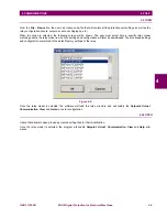
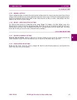
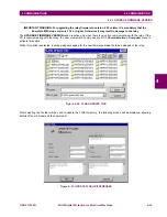
When one of the logics is selected, a new window will appear where the user can assign up to 8 inputs to the logic circuit.
Each of these inputs can be a single function or status, as well as a logical union of several statuses.
Figure 4–13: LOGIC CONFIGURATION
The way the logic works is illustrated in the diagram at the right of the logic window.
First, depending on the gate, up to 2 or 3 signals (internal flags coming from the status of the relay or from another logic,
or external input signals) can be chosen as sources of each
AND gate
. The way they are programmed is similar to the
way I/Os are (refer to relay configuration). The device will not take into account entries that are after an empty one. This
means that every entry after the first empty one will be ignored. For example, if
L1 IN1
is programmed but
L1 IN2
is left
empty, the relay will not take into account
L1 IN3
and will directly evaluate
L1 IN4
. In the same way, the relay will ignore
AND2
if
AND1
is not programmed, and will ignore
AND3
if
AND1
or
AND2
are not programmed.
Then the results from the AND gates are added by an
OR gate
that will produce the result of the logic.
It is possible to set the
pickup and dropout times for output from the OR gate.
Example: for picking time of 10s and a
dropout time of 15s, if input of the OR gate changes to 1, this input has to remain for 10s before the result of the logic
changes to 1. If result of the OR gate drops to 0, output will be 1 for 15s and after that time output will be 0.
See Chapter 7 for more details on logic configuration.
Summary of Contents for Multilin MIGII
Page 2: ......


