


66
GENERAL
D400 SUBSTATION GATEWAY USER’S MANUAL
D400 SYSTEM REDUNDANCY
CHAPTER 4: CONNECTING TO DEVICES AND NETWORKS
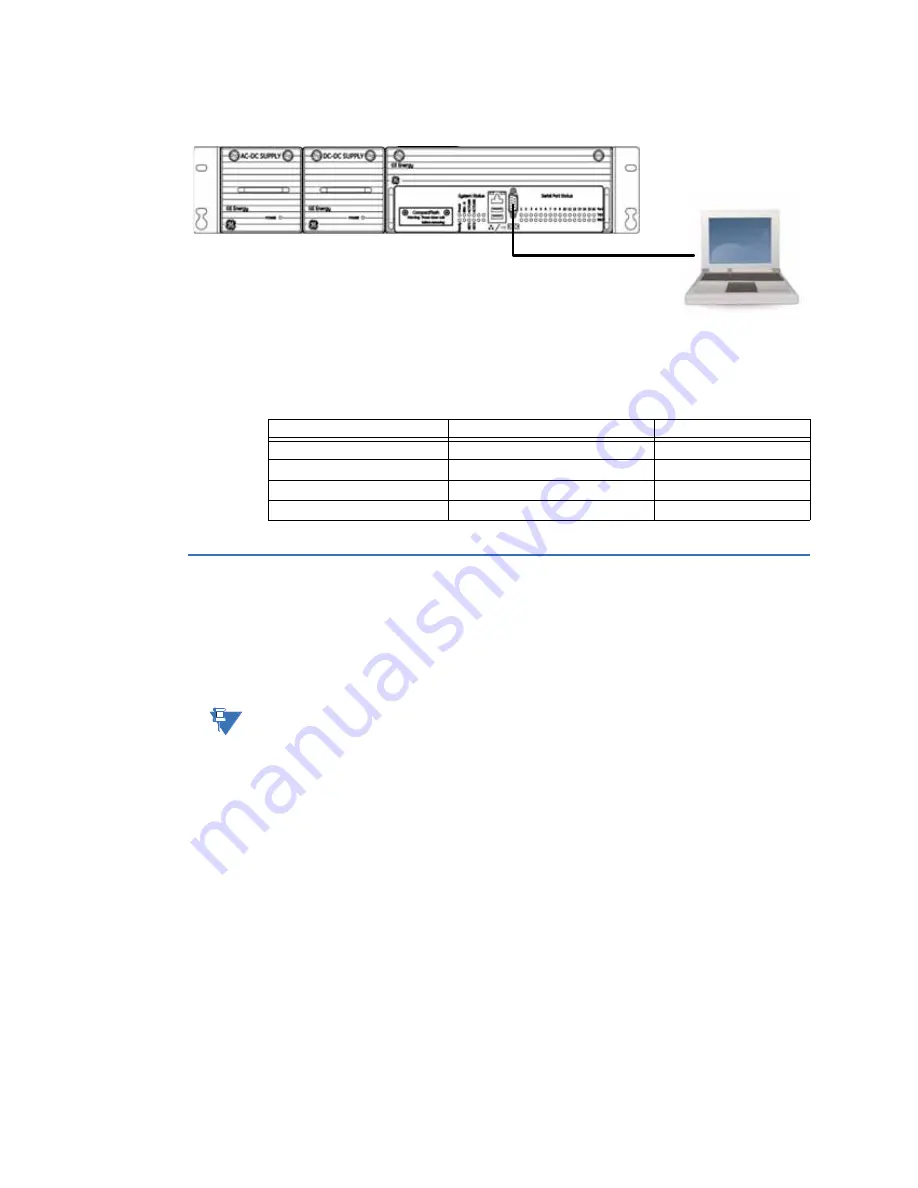
Figure 41: Front serial port
Minimal required connection
The minimal cable connection required to establish successful communication between
your PC and the D400 is as follows:
D400 system redundancy
A redundant D400 setup allows a secondary D400 to automatically take over operations
from a paired D400 unit that has failed.
D400 equipment redundancy requires two D400 units and one or two RS232 switch panels.
The RS232 switch panel is mandatory for Warm Standby redundancy.
NOTE
If the Hot Standby redundancy feature is available, the RS232 switch panel is optional.
A pair of LEDs marked
CCU A
and
CCU B
indicate which of the D400 units is currently active.
If the hardware or software of the active unit fails, it is automatically switched offline and
serial connections to the field are transferred to the standby unit. A toggle switch on the
RS232 switch panel can be used to switch the D400 devices between active and standby
modes.
Failover sequence
If the active D400 unit fails, the following actions occur:
1.
The standby D400 unit detects the failure through the lack of a heartbeat signal on the
ping cable or through a status change on the watchdog cable.
2.
The standby D400 unit attempts to pull the RS232 switch panel to assume the active
state.
3.
The RS232 switch panel transfers all serial field connections to the standby D400,
which then becomes the active D400.
PC Pin #
D400 Pin #
Signal Acronym
9-Pin Female
9-Pin Female (w/o Converter)
2
3
TXD
3
2
RXD
5
5
GND