MicroVersaTrip Plus™ and MicroVersaTrip PM™ Trip Units
Chapter 2. Setup Mode
24
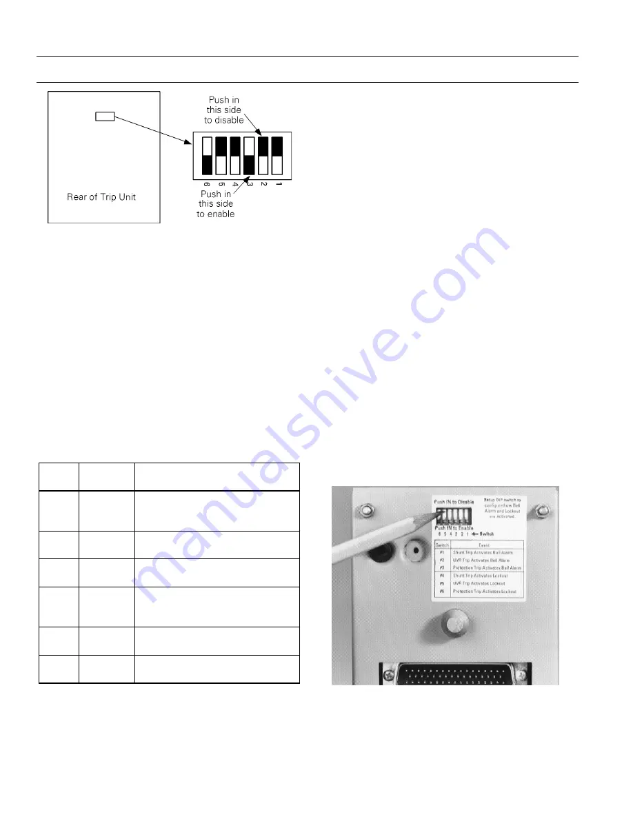
Figure 45. Accessory configuration switch on rear of Trip Unit,
showing factory settings (solid part indicates that switch is
pushed in on that side).
Description of Switch Settings
Following are descriptions of the effects of each
accessory switch when it is
enabled:
1
1
1
1.... When a Shunt Trip or Shunt Trip with Lockout
accessory causes the breaker to trip, the
contacts of the Bell Alarm–Alarm Only also
change state. The factory switch setting is
disabled.
2
2
2
2.... When an Undervoltage Release accessory
causes the breaker to trip, the contacts of the
Bell Alarm–Alarm Only also change state. The
factory switch setting is
disabled.
SS
S
Sw
w
w
wiiiittttccc
ch
h
h
h
F
F
F
Faa
a
accc
ctttto
o
o
orrrryyyy
SS
S
Seee
ettttttttiiiin
n
n
ng
g
g
g
F
F
F
Fu
u
u
un
n
n
nccc
cttttiiiio
o
o
on
n
n
n
1
Disabled
Shunt Trip or Shunt Trip with
Lockout activates Bell
Alarm–Alarm Only
2
Disabled
UVR trip activates Bell
Alarm–Alarm Only
3
Enabled
Protection trip activates Bell
Alarm–Alarm Only
4
Disabled
Shunt Trip or Shunt Trip with
Lockout activates Bell Alarm with
Lockout
5
Disabled
UVR trip activates Bell Alarm with
Lockout
6
Enabled
Protection trip activates Bell
Alarm with Lockout
Table 17. Accessory configuration switch settings, including
factory defaults.
3
3
3
3.... When a protection trip (long-time, short-time,
instantaneous, ground-fault, or protective-
relay) occurs, the contacts of the Bell
Alarm–Alarm Only also change state. The
factory switch setting is
enabled.
4
4
4
4.... When the Shunt Trip or Shunt Trip with
Lockout accessory causes the breaker to trip,
the contacts of the Bell Alarm with Lockout
also change state. The factory switch setting is
disabled.
5
5
5
5.... When the Undervoltage Release accessory
causes the breaker to trip, the contacts of the
Bell Alarm with Lockout also change state. The
factory switch setting is
disabled.
6
6
6
6.... When a protection trip (long-time, short-time,
instantaneous, ground-fault, or protective-
relay) occurs, the contacts of the Bell Alarm
with Lockout also change state. The factory
switch setting is
enabled.
To change switch settings on RMS9D series Trip
Units, refer to Chapter 5 to remove the Trip Unit
from the breaker. Push in the appropriate Enable or
Disable side of the switch to configure the accesso-
ries, as shown in Figure 46, and carefully reinstall the
Trip Unit. Verify that the new switch settings are
correct by testing the breaker responses to
Undervoltage Release trips and Shunt trips.
Figure 46. Setting the accessory configuration switches.


