20
MDS TransNEXT Technical Manual
MDS 05-7280A01, Rev. A
NOTE
To prevent moisture from entering the unit, do not mount the case with the cable connectors
pointing up. Also, dress all cables to prevent moisture from running along the cables and into
the unit.
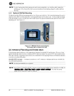
Optional DIN Rail Mounting
If ordered with the DIN rail mounting option, two choices are available. For vertical mounting the unit is
supplied with a DIN rail clip attached to an integrated bracket on the unit’s case. For horizontal mounting
a special bracket is used. In both cases the bracket allows for quick installation and removal from a DIN
mounting rail. See Figure 2-7.
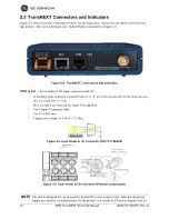
Figure 2-7. DIN Rail Attachment examples
(Pull down tab to release from rail)
2.6 Antenna Planning and Installation
Consideration must be taken to select appropriate antennas for optimal RF performance. The use of non-
approved antennas may result in a violation of FCC rules and subject the user to FCC enforcement action.
Note that with any installation, there needs to be a minimum 20 cm spacing between all transmit antennas
to avoid co-location difficulties.
900 MHz ISM Antennas
—Antenna connection is a TNC connector. Multiple options are available for
this unlicensed operation.
NOTE
Professional installation is required.
NOTE
For regions governed by FCC/IC compliance the maximum EIRP must be limited to 36 dBm. If
(
(antenna gain - feed line loss) + power output setting)
>36), then the power
output of the TransNEXT must be reduced.
Summary of Contents for MDS TransNEXT NET9L
Page 55: ...MDS 05 7280A01 Rev A MDS TransNEXT Technical Manual 55...
Page 58: ...58 MDS TransNEXT Technical Manual MDS 05 7280A01 Rev A...
Page 61: ...MDS 05 7280A01 Rev A MDS TransNEXT Technical Manual 61...
Page 66: ...66 MDS TransNEXT Technical Manual MDS 05 7280A01 Rev A NOTES...
Page 67: ...MDS 05 7280A01 Rev A MDS TransNEXT Technical Manual 67...
Page 69: ......

