MDS 05-7280A01, Rev. A
MDS TransNEXT Technical Manual
19
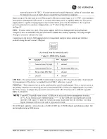
The LEDs are multi-color to convey different types of status conditions as shown in the following chart:
Table 2-4. Description of LED Status Indicators
LED Name
LED State
Description
PWR
(DC Power)
Off
Solid Green
Flashing Red
(0.5s ON/ 0.5s OFF)
Flashing Green
(0.5s ON/ 0.5s OFF)
Fast Alternating
(Red/Yellow/Green)
No power to unit.
Unit is powered, no problems detected.
Alarm indication.
Unit is being programmed.
Unit is booting up.
RADIO-1
(master)
(remote)
(all)
Off
Solid Green + flicker
Solid Color + flicker on data
[
Color based on RSSI]
Green:
Yellow:
Violet:
Red:
Flashing Red
(1.0s ON/1.0s OFF)
Multi-Color (rotating)
(1.0s ON per color)
Interface disabled.
Radio-1 will flicker on data.
Radio-1 is synchronized to a master.
LED will flicker on data.
RSSI >= -70 dBm
-70 dBm < RSSI <= -85 dBm
-85 dBm < RSSI <= -100 dBm
RSSI < -100 dBm
Remote radio is not synchronized.
Radio is in
setup
mode.
RADIO-2
(if equipped)
Off
Interface disabled.
2.4 Grounding Considerations
To minimize the chance of damage to the unit and its connected equipment, a safety ground (NEC Class 2
compliant) is recommended, which bonds the chassis, antenna system(s), power supply and connected
data equipment to a
single-point
ground, keeping all ground leads as short as possible.
Normally, the unit is adequately grounded if mounted with the flat brackets to a well-grounded metal
surface. If the unit is not mounted to a grounded surface, it is recommended that a safety ground wire be
attached to the screw provided on the bottom corner of the enclosure, in the recessed flat area.
Alternatively, a safety ground wire may be attached to one of the mounting bracket screws.
The use of a lightning protector is recommended where the antenna cable enters the building; Bond the
protector to the tower ground, if possible. All grounds and cabling must comply with applicable codes
and regulations. One source for lightning protection products may be found online at
http://www.protectiongroup.com/PolyPhaser
2.5 Mounting Options
The unit may be mounted with flat mounting brackets
or
an optional 35 mm DIN rail attachment.
Summary of Contents for MDS TransNEXT NET9L
Page 55: ...MDS 05 7280A01 Rev A MDS TransNEXT Technical Manual 55...
Page 58: ...58 MDS TransNEXT Technical Manual MDS 05 7280A01 Rev A...
Page 61: ...MDS 05 7280A01 Rev A MDS TransNEXT Technical Manual 61...
Page 66: ...66 MDS TransNEXT Technical Manual MDS 05 7280A01 Rev A NOTES...
Page 67: ...MDS 05 7280A01 Rev A MDS TransNEXT Technical Manual 67...
Page 69: ......

