


05-4847A01, Rev. D
MDS SD Series Setup Guide
3
2.2
Initial Checkout
In-service operation of the transceiver is completely automatic.
The only operator actions required are to apply DC power and
observe the LEDS for proper indications.
Table 1
summarizes the
radio’s LED functions.
2.2.1
LED Functions
NOTE:
LED labeling may vary on early units. LED position and
functionality remains as described below.
Figure 9. LED Status Indicators
Table 1: Description of LED Status Indicators
NOTE:
In addition to the LEDs above, the Ethernet connector
also has two embedded LEDs. A flashing green indicates
Ethernet data activity. A yellow indicates 100 Mbps oper-
ation.
2.2.2
Antenna SWR Check
The antenna system’s standing wave ratio (SWR) should be
checked on new installations using a wattmeter suited to the fre-
quency of operation. High SWR (above 2:1) may indicate an
antenna or feedline problem.
2.2.3
RSSI Check (for Remotes)
Using the
Maintenance & Status>>Performance
screen, check
the received signal strength indication (RSSI). The radio must be
receiving a signal from the associated Master Station (LINK LED
on or blinking). In general, signal levels stronger than –80 dBm will
provide reliable communication and allow for a degree of “fade
margin.”
Optimize the RSSI at Remotes by slowly adjusting the direction of
the station antenna. Watch the RSSI indication for several seconds
after making each adjustment, so that the RSSI accurately reflects
the new heading. With RSSI readings, the less negative the
number, the stronger the incoming signal.
NOTE:
The radio’s RSSI facility limits the maximum displayed
signal strength to -60 dBm. A receive signal attenuator is
available in the
Configuration>>Radio>>Advanced
Settings
screen.
All radios in the network must meet the basic requirements listed
below for proper operation. Check these items first when trouble-
shooting a system problem:
• Adequate and stable primary power
• Secure connections (RF, data and power)
• A clear transmission path between Master and each Remote
• An efficient and properly aligned antenna system providing
adequate received signal strength.
• Proper programming of radio settings
• The correct interface between the transceiver and the con-
nected data equipment (correct cable wiring, proper data
format, timing, etc.)
3.1
LEDs
The radio’s LED indicator panel provides useful information when
troubleshooting a system problem. Refer to
Table 1
for LED indi-
cations.
3.2
Event Codes
When an alarm condition exists, the transceiver creates a mes-
sage readable on the
Maintenance & Status
Screen. From this
screen, select
Event Log
to view the current alarm(s). Consult the
Technical Manual
for details.
3.2.1
Types of Alarms
Minor Alarms—
These alarms report conditions that, under most
circumstances will not prevent transceiver operation. This includes
out-of-tolerance conditions, baud rate mismatches, etc. The cause
should be investigated and corrected to prevent system failure.
Major Alarms
—These alarms report serious conditions that gen-
erally indicate a hardware failure, or other abnormal condition that
will prevent (or seriously hamper) further operation of the trans-
ceiver. Major alarms may require factory repair. Contact your fac-
tory representative for assistance.
3.3
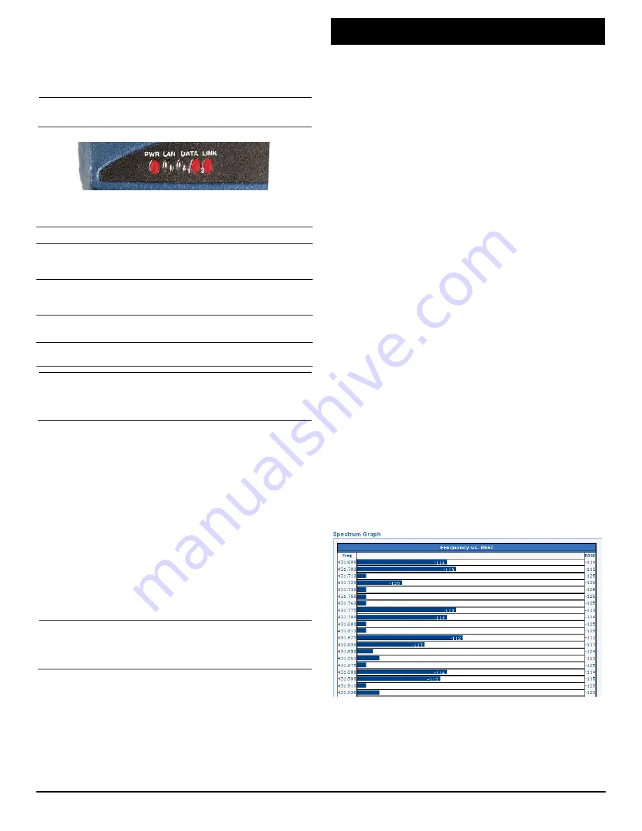
Built-In Spectrum Analyzer/Graph
A Spectrum Analyzer/Graph is available to display other radio sig-
nals near the SD radio’s operating frequencies. This can be a
helpful tool in cases of interference. The graph may be accessed
from the
Maintenance & Status>>Radio Test
screen.
To use the graph, simply enter the frequency you wish to use as
the center point of the graph (
Center Frequency
), and enter the
frequency range you wish to cover (
Span Frequency
). Select
Show Spectrum
to display the results.
The display creates a received signal strength indication (in dBm)
vs. frequency plot for signals near the center frequency (see
Figure 10
).
Invisible
place
holder
Figure 10. Spectrum Analyzer/Graph (Portion of Display)
LED Name
Description
PWR
• Continuous—Power applied, no problems detected.
• Rapid flash (5 times-per-second)—Alarm
indication.
LAN
• Flashing—Ethernet data activity is detected.
• Off—Ethernet signals not detected, or excessive
traffic is present.
DATA1/DATA2
The DATA LEDs show data activity on the DB-9
serial payload port(s).
LINK
When lit, indicates that a communication link exists
with the another station.
3.0
TROUBLESHOOTING


