H3C RA100, Installation Manual
The ACME RA100 User Manual is a comprehensive guide designed to assist you in maximizing the functionality of your RA100 device. Easily downloadable and completely free, this manual is a valuable resource for understanding every feature and operation of your product. Download it now at manualshive.com.
Share
Download


Reviews:
No comments
Related manuals for RA100

KX-UDS124
Brand: Panasonic Pages: 24

i-Pro WV-SP302
Brand: Panasonic Pages: 2

BB-HCM381A - Network Camera
Brand: Panasonic Pages: 28

BB-HCM381A - Network Camera
Brand: Panasonic Pages: 2

8 Port 10/100Mbit/s Ethernet Smart Switch with Fibre Uplink
Brand: Tyco Electronics Pages: 18

WNAP4G
Brand: A-Link Pages: 6

7707
Brand: Keithley Pages: 59

Talari E1000
Brand: Oracle Pages: 24

ADSL/ADSL2/ADSL2+ Router 660R-6xC Series
Brand: ZyXEL Communications Pages: 282

Yaskawa 2000
Brand: red lion Pages: 5

PXI PXITM -1000
Brand: National Instruments Pages: 55
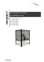
AceroDURO 100/S100
Brand: CNC-Step Pages: 86

T1L2PY0AA
Brand: PairGain Pages: 80

RBRE960B
Brand: NETGEAR Pages: 152

COM-840
Brand: Steren Pages: 130

D-PK-NG432
Brand: DPS Telecom Pages: 80

NBG6616
Brand: ZyXEL Communications Pages: 4

N-FXE-xxx-01
Brand: Transition Networks Pages: 5


