GE H
EALTHCARE
D
IRECTION
5162630, R
EVISION
3
LOGIQ™ S6 S
ERVICE
M
ANUAL
4-18
Section 4-2 - General Procedure
4-3-3
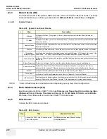
Mode Checks (QG)
For a functional check of the system’s different modes, refer to the LOGIQ™ S6 Quick Guide. The Quick
Guide will familiarize you with image optimization for
B-Mode
,
M-Mode
,
Color Flow
, and
Doppler
.
4-3-3-1
System Checks
NOTE:
* Some software may be considered standard depending upon system model configuration.
4-3-4
Basic Measurements (QG)
Basic Measurements for the LOGIQ™ S6 include
Distance and Tissue Depth
,
Circumference/Area
(Ellipse and Trace)
,
Volume
,
Time Interval
,
Velocity
,
PI
,
RI
,
S/D Ratio
,
D/S Ratio
, and
A/B Ratio
.
Information for all these tests is found in the LOGIQ™ S6 Quick Guide.
4-3-5
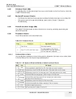
ECG Checks
Connect the ECG Harness and check:
Table 4-38 System Functional Checks
÷
Step
Description
B-Mode
Verify basic B-Mode (2D) operation. Check the basic system controls that affect this mode of
operation.
CF-Mode
Verify basic CF-Mode (Color Flow Mode) operation. Check the basic system controls that affect this
mode of operation.
Doppler Modes
Verify basic Doppler operation (PW and CW if available). Check the basic system controls that affect
this mode of operation.
M-Mode
Verify basic M-Mode operation. Check the basic system controls that affect this mode of operation.
*Applicable
Software Options
Verify the basic operation of all optional modes such as Multi-Image, 3D, Contrast, Harmonics, Cine,
Stress Echo,... etc. Check the basic system controls that affect each options operation.
Probe Elements Perform an Element Test on each probe to verify that all probe elements (and system channels) are
functional.
System Diagnostic Perform the Automatic Tests to verify that all boards function according to specifications.
Control Panel Test Perform the Control Panel Test Procedure to verify that all keyboard controls are OK. This is
performed by the internal PC (backend processor) which does a normal keyboard run through.
Monitor
Verify basic Monitor display functions. Refer to Chapter 3 of the User Manual.
Touch Panel
Verify basic Touch Panel display functions. Refer to Chapter 3 of the User Manual.
Measurements
Scan a gray scale phantom and use the measurement controls to verify distance and area calculation
accuracy. Refer to the User Manual, Chapter 18, for measurement accuracy specifications.
Table 4-39 ECG Control
Step
Task
Expected Result(s)
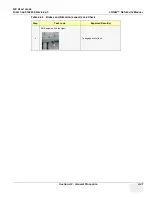
1
Connect the ECG at the Connector on the
Front of the system
It will display a curve along the bottom edge
of the image sector

