5–58
LM10 MOTOR PROTECTION SYSTEM – INSTRUCTION MANUAL
DEVICENET OPERATIONS
CHAPTER 5: COMMUNICATIONS
F9: Auxiliary Sense 1 / Run1-Run2 Time Delays
Format: two bytes in format 0xHHLL, where LL is the auxiliary sense 1 time delay and HH is
the Run1-Run2 time delay (Run1-Run2 time delay for revisions 1.40 and lower only)
Byte LL range: 0x00 to 0xFA (i.e. 0.0 to 25.0 seconds), where 0x00 is disabled
Byte LL multiplying factor: 0.1 (i.e. actual = byte LL in decimal
×
0.1 seconds)
Byte HH range: 0x00 to 0xB4 (i.e. 0 to 180 seconds)
F10: Auxiliary Sense 2 / Run2-Run1 Time Delays
Format: two bytes in format 0xHHLL, where LL is the auxiliary sense 2 time delay and HH is
the Run2-Run1 time delay (Run2-Run1 time delay for revisions 1.40 and lower only)
Byte LL range: 0x00 to 0xFA (i.e. 0.0 to 25.0 seconds), where 0x00 is disabled
Byte LL multiplying factor: 0.1 (i.e. actual = byte LL in decimal
×
0.1 seconds)
Byte HH range: 0x00 to 0xB4 (i.e. 0 to 180 seconds)
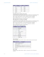
F11: Auxiliary Relay Faults (16-bit bitmask)
F12: Starter Type
Format: two bytes in format 0xHHLL, where LL is the motor type and HH is reserved
Byte LL enumeration:
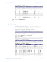
F13: CT Turns
Format: two bytes in format 0xHHLL, where LL is the number of CT turns and HH is
reserved
2
90 A sensor pack
10
300:5
3
75:5
11
400:5
4
100:5
12
500:5
5
120:5
13
600:5
6
150:5
14
700:5
7
200:5
15
800:5
8
225:5
Bitmask
Fault
---- ---- ---- ---1
Overcurrent
---- ---- ---- --1-
Reserved
---- ---- ---- -1--
Jam
---- ---- ---- 1---
Stall
---- ---- ---1 ----
Current unbalance
---- ---- --1- ----
Aux sense
---- ---- -1-- ----
Load loss
---- ---- 1--- ----
Reserved
---- ---1 ---- ----
Reserved
---- --1- ---- ----
DeviceNet
---- -1-- ---- ----
Voltage range
Value
Starter Type
0
FVNR (full voltage non-reversing)
1
FVR (full voltage reversing)
2
RV (reversing)
3
2S1W (two-speed one winding; Run-2, 4:1 ratio of Run-1)
4
2S2W (two-speed two winding; Run-2, 2:1 ratio of Run-1)
5
Custom
Value
CT Ratio
Value
CT Ratio
Summary of Contents for LM10
Page 6: ...1 IV LM10 MOTOR PROTECTION SYSTEM INSTRUCTION MANUAL TABLE OF CONTENTS ...
Page 18: ...1 12 LM10 MOTOR PROTECTION SYSTEM INSTRUCTION MANUAL SPECIFICATIONS CHAPTER 1 INTRODUCTION ...
Page 70: ...5 64 LM10 MOTOR PROTECTION SYSTEM INSTRUCTION MANUAL SERIAL PORT CHAPTER 5 COMMUNICATIONS ...
Page 74: ...6 68 LM10 MOTOR PROTECTION SYSTEM INSTRUCTION MANUAL WARRANTY CHAPTER 6 MISCELLANEOUS ...
Page 106: ...I 4 LM10 MOTOR PROTECTION SYSTEM INSTRUCTION MANUAL INDEX ...


