


Service Manual
I4X/EN CO/D
ISTAT I4X
Page 12
8.
CONNECTION MODES
8.1
EIA (RS)232 to EIA (RS)485
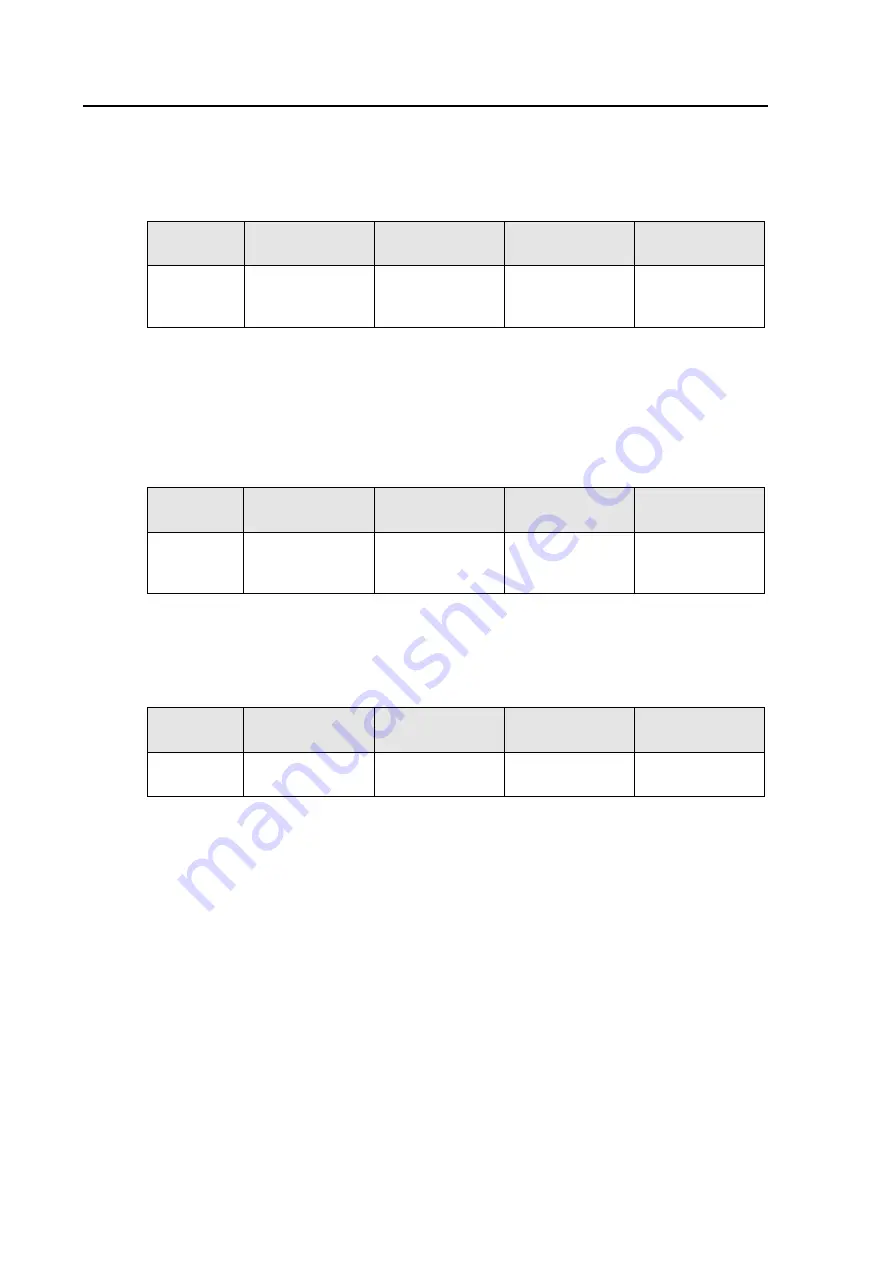
There are three groups of terminals on the I4X; the auxiliary voltage, the RS232 port and the
RS485 port. These are shown in the table below:
I4X
Auxiliary supply
RS232
port
RS485
port
Output device
Screw
Terminals
13 +
∼
, 14
–
∼
(TX) 26
(RX) 24
(GND) 25
(A) 21
(B) 23
DATA +
DATA -
The maximum cable length between the I4X and the RS232 device is 3 meters.
The maximum number of devices that can be supported using RS485 communications is 32.
The line should be terminated by a 120 ohm resistor.
8.2
Ethernet to EIA (RS)232
There are three groups of terminals on the I4X; the auxiliary voltage, the Ethernet port and
the RS232 port. These are shown in the table below:
I4X
Auxiliary supply
Ethernet
port
RS232
port
Output device
Terminals
13 +
∼
, 14
–
∼
10/100 RJ45
socket
(TX) 26
(RX) 24
(GND) 25
(TX)
(RX)
(GND)
The maximum cable length between the I4X and the RS232 device is 3 meters.
8.3
Ethernet to EIA (RS)485
There are three groups of terminals on the I4X; the auxiliary voltage, the Ethernet port and
the RS485 port. These are shown in the table below:
I4X
Auxiliary supply
Ethernet
port
RS485
port
Output device
Terminals
13 +
∼
, 14
–
∼
10/100 RJ45
socket
(A) 21
(B) 23
DATA +
DATA -
The maximum number of devices that can be supported using RS485 communications is 32.
The line should be terminated by a 120 ohm resistor.
8.4
Status Indication: Power
On each I4X there is a single Power LED that indicates when there is an auxiliary supply
connected. The I4X uses a universal ac/dc power supply that can operate between 24 to
300V DC and 40 to 276V AC. The frequency range of the power supply is 40 to 70Hz.


