background image


GE MDS Intrepid-HC HP Installation Guide

 2-19


Important:

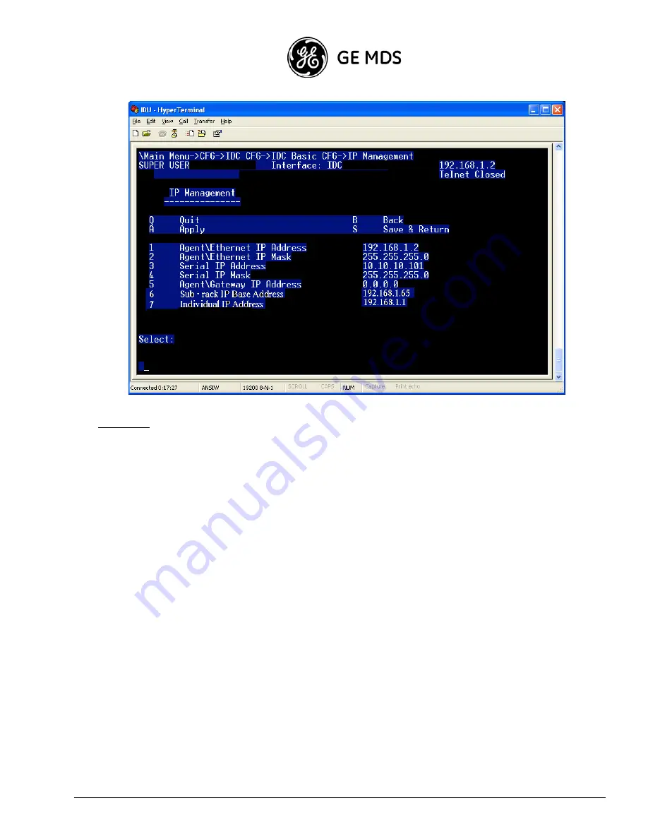
 After you set up IP addresses, restart the IDUs to activate them. 

7. 

Repeat the steps above for the remaining IDCs in the Intrepid-HC HP/T IDU. 

Setup Options in the Terminal Program 

The main menu in the terminal setup program includes the following options: 

Configuration (1)

 - the main setup section in which you can configure the IDC, the right and left drawers, 

protection, SNMP management, in-band routing, and other such parameters. 

System Status (2)

 - used to obtain information about the different software versions currently used in the system. 

Maintenance (3)

 - used to perform software upload, download, and reset. 

Diagnostics (4)

 - used to perform loopbacks and obtain system information. 

Logs (5)

 - used to view alarm and configuration log reports. 

Summary of Contents for HC HP

Page 1: ...GE MDS Intrepid HC HP Wireless Broadband Transceiver Version 1 x Reference Manual Part 05 4811A01 Rev A ...

Page 2: ......

Page 3: ...id HC HP T 2 14 Connecting Line Interfaces 2 32 Chapter 3 Acceptance Commissioning Procedures 3 1 Site Acceptance Procedure 3 2 1 0 Commissioning Procedure 3 7 1 1 Commissioning Procedure 3 9 2 0 XPIC Commissioning Procedure 3 12 GE MDS Intrepid HC HP Commissioning Log 3 15 Appendix A Connector Pin Outs A 1 General A 1 External Alarms Connector Pin Out A 2 Protection Connector Pin Out A 3 Modem PP...

Page 4: ...se eye hazard CLASS 1 LASER PRODUCT Complies with IEC 60 825 1 1993 A1 1997 A2 2001 and EN 60825 1 1994 A1 1996 A2 2001 General Equipment Precautions Use of controls adjustments or performing procedures other than those specified herein may result in hazardous radiation exposure When working with an IDU note the following risk of electric shock and energy hazard Disconnecting one power supply disc...

Page 5: ...ing components inside the device all electrostatic must be discharged from both personnel and tools RoHS Compliance Declaration 子信息 品有毒有害物 申明 Electronic Information Products Declaration of Hazardous Toxic Substances Hazardous Substance Component Lead Pb Mercury Hg Cadmium Cd Hexavalent Chromium Cr VI Polybrominated Biphenyls PBB Polybrominated Diphenyl Ethers PBDE PCB Circuit Modules Comply Comply...

Page 6: ......

Page 7: ...nsceiver units operate in the frequency range of 6 11 GHz GE MDS Intrepid HC HP capacities can be upgraded from 45 Mbps up to N x 155 Mbps For long distance links and backbone requirements GE MDS Intrepid HC HP offers Space Diversity functionality Each transceiver can contains two receivers and one transmitter which enable built in diversity capability Built in Diversity in each transceiver increa...

Page 8: ...ve alternative to fiber GE MDS Intrepid HC HP T all indoor trunked unit is a high capacity N 1 trunk radio system that was designed to support multiple capacities frequencies modulation schemes and configurations for various network requirements GE MDS Intrepid HC 64P is a high capacity PDH radio designed for seamless upgrade from medium to high capacity with a built in Fast Ethernet port and swit...

Page 9: ...ifference between the two types are the circulator directions Depending on the configuration OCB Type 1 or Type 2 are used together with waveguide shorts waveguide loads U Bends C Bends or couplers Each OCB has four waveguide access points two in the front and two at the rear The diversity access point is optional If the system is not configured for diversity all the relevant access points on the ...

Page 10: ...include the following RFU OCB Hanger Kit Pole Mount Kit Assembling the RFU and OCB The RFU is generally assembled in the factory with the OCB and delivered as a single unit If the RFU is delivered separately with the OCB do the following Important The instructions in this guide should be performed indoors 1 Remove the RFU and the OCB from the box 2 Make sure that the OCB sealing gasket is in place...

Page 11: ...lation Guide 1 5 3 Gently slide the RFU in the OCB making sure that the two empty spaces in the RFU correspond to the filter positions on the OCB 4 Tighten the Allen Head screws to the OCB using an Allen wrench OCB Sealing Gasket ...

Page 12: ... Hanger Kit together with the RFU and OCB 1 Place the RFU on the floor and hold it upright as shown in the photo below 2 Place the Hanger Kit in line with the OCB as shown in the illustration below and fasten the Kit to the OCB using 3 large M 10 type screws Allen Head Screws Hanger Bend to place on the Pole Kit Main Extension Diversity Extension Three Screws Fastening the Hanger Kit to the OCB ...

Page 13: ... plate with a clamp assembly Important The diameter of the pole upon which the kit is mounted must be between 50 mm 2 and 125 mm 5 To assemble the Pole Mount Kit on the pole 1 Open the Pole Mount Kit clamp and assemble the kit on the pole as shown in the following illustration 2 Fasten the kit to the pole using the 4 screws as shown in the photo above Four Screws Fastening the Pole Mount Kit to th...

Page 14: ... Pole Mount Kit To assemble the Hanger Kit and the Pole Mount Kit 1 Lift the Hanger Kit with the fastened RFU and OCB and hang it using the Hanger Bend on the Pole Mount Kit as shown in the following illustrations Hanger Bend Side view showing how the Hanger Kit is hung on the Pole Mount Kit ...

Page 15: ...ation Guide 1 9 2 Fasten the Hanger Kit to the Pole Mount Kit using 4 large M 10 type screws as shown in the following illustration Screws fastening the Hanger Kit to the Side view of the Hanger Kit assembled on the Pole Mount Kit ...

Page 16: ...GE MDS Intrepid HC HP Installation Guide 1 10 Each Pole Mount Kit can accommodate two RFUs and OCB units as shown in the following illustration Couplers ...

Page 17: ...ted on the bottom of the RFU as shown in the following photo The connections include the following XPIC RSL For XPIC functionality and radio signal monitoring IF Connects the RFU to the IDU Ground Used for electrical ground Flexible Waveguide Connects the RFU to the antenna IF XPIC RSL Waveguide Ground ...

Page 18: ...section describes the installation procedure for GE MDS Intrepid HC HP in a 2 2 XPIC configuration Flexible Waveguide Connection to Main Horizontal and Vertical Antenna Ports Elliptical Waveguide Waveguide to Coax Connection to Diversity Horizontal and Vertical Antenna Ports ...

Page 19: ...the pole If the RFUs are to be assembled one above the other there should be a minimum distance of 40 cm between the two pole mount kits as shown in the following illustration 40 cm M10 Screws Fastening the OCB to the Hanging Bracket Hanging Bracket Lifting Handle Pole Mount Kit with Clamp Bracket Diversity Coupler Main Coupler ...

Page 20: ... Assemble both couplers on the OCBs 4 Attach the hanging bracket to the OCBs and tighten the screws that fasten the OCB to the hanging bracket 5 Gently lift the assembled unit to the pole using the lifting handle 6 Place the assembled units on the pole mount clamp bracket and fasten the M10 screws as shown in the following illustration 7 Connect the XPIC cables between the units as shown in the fo...

Page 21: ...guides to the antennas as shown in the illustration above V and H poles are selected as required in the illustration above they are selected arbitrarily Main Antenna H Pole Port Diversity Antenna H Pole Port XPIC Cables Main Antenna V Pole Port Diversity Antenna V Pole Port ...

Page 22: ...nected via U bends at the rear extension ports The third OCB is chained to the second OCB through the main and diversity ports using a flexible waveguide Each OCB is connected to the relevant IF cable from the Intrepid HC HP T Baseband Indoor The following example shows a 4 1 space diversity dual pole configuration To Diversity V Antenna To Main V Antenna To Main H Antenna Termination Flexible Wav...

Page 23: ...allation Guide 1 17 Note When installing an N 1 configuration assemble the OCBs in an inverted order to maintain the same branching loss between the carriers as shown in the following illustration Site A Site B C1 C2 C3 C3 C2 C1 ...

Page 24: ...ent GE MDS Intrepid HC HP installation configurations Note that in this section the following abbreviations are used HSB Hot Standby FD Frequency Diversity SD Space Diversity DP Dual Pole MP Main Path SP Secondary Path MA Main Antenna DA Diversity Antenna N A Not Applicable WG Waveguide X Y dB X refers to 6 8 GHz Y refers to 11 GHz ...

Page 25: ...1 0 Configuration 1 0 SD Configuration B L W G M P S P 1 0 M A D A M A D A 0dB 0 5dB N A N A N A N A N A N A B L W G M P S P 1 0SD M A D A M A D A 0 5dB 0dB 1 5 2 5dB N A N A N A N A 0dB CoaxCable3 5 5dB SP Antenna 1 IDC Chassis 1 IDM 155 1 TX Filter RX Filter RX Filter TX RX M RX D TX f1 RX f1 RX f1 OCB type 1 50 ohm 50 ohm RFU Eliptical WG orCoaxCable FlexibleWG ...

Page 26: ... f1 RFU 50 oh m OCB type 2 50 oh m Flexible WG PoleMount 1 50ohm Termination 2 Short 4 Coupler Type1 1 Flex WG1 2m 1 SP Antenna 1 IDC Chassis 1 IDM 155 2 ProtectionKit 1 1 1 SD Configuration B L W G M P S P 1 1SD M A D A M A D A 1 6 1 8dB 0 5dB 7 7 4dB 0 5dB 1 6 1 8dB 1 5 2 5dB CoaxCable3 5 5dB 1 6 1 8dB 1 5 2 5dB TX Filter RX Filter RX Filter TX RX M RX D TX f1 RX f1 RX f1 OCB type 2 RFU TX Filte...

Page 27: ...1 TX Filter RX Filter RX Filter TX RX M RX D TX f3 RX f3 RX f3 OCB type 2 RFU TX Filter RX Filter RX Filter TX RX M RX D TX f1 RX f1 RX f1 OCB type 1 RFU 50 ohm FlexibleWG B L W G M P S P 1 0SD M A D A M A D A 0 5dB 0 25dB 1 5 2 5dB N A N A N A N A 0 25dB CoaxCable3 5 5dB 1 1FD SD Configuration TX Filter RX Filter RX Filter TX RX M RX D TX f3 RX f3 RX f3 OCB type 2 8GHz RFU U bends WG TX Filter RX...

Page 28: ...B L W G M P S P 1 0SDBBS M A D A M A D A 0dB 0 5dB N A N A N A N A 0dB 0 5dB TX Filter RX Filter RX Filter TX RX M RX D TX f1 RX f1 RX f1 OCB type 1 RFU 50 ohm TX Filter RX Filter RX Filter TX RX M RX D TX f1 RX f1 RX f1 OCB type 1 50 ohm RFU Main antenna Diversity antenna FlexibleWG FlexibleWG ...

Page 29: ... N A N A N A N A N A TX Filter RX Filter RX Filter TX RX M RX D TX f1 RX f1 RX f1 OCB type 1 RFU 50 ohm TX Filter RX Filter RX Filter TX RX M RX D TX f1 RX f1 RX f1 OCB type 1 RFU 50 ohm FlexibleWG Flex WG 1 2m 2 DP Antenna 1 XPIC cable3m long 1 IDC Chassis 1 IDM 155 2 TX Filter RX Filter RX Filter TX RX M RX D TX f1 RX f1 RX f1 OCB type 1 RFU 50 ohm TX Filter RX Filter RX Filter TX RX M RX D TX f...

Page 30: ...0 ohm 50 ohm Eliptical WG or CoaxCable FlexibleWG B L W G M P S P 2 0 SD SPA M A D A M A D A 0 5dB 0 25dB 1 5 2 5dB N A N A N A N A 0 25dB CoaxCable3 5 5dB PoleMount 1 50ohm Termination 1 Short 4 U BendW G Type1 1 Flex W G 1 2m 1 SP Antenna 1 IDC Chassis 1 IDM 155 2 TX Filter RX Filter RX Filter TX RX M RX D TX f2 RX f2 RX f2 OCB type 2 RFU TX Filter RX Filter RX Filter TX RX M RX D TX f1 RX f1 RX...

Page 31: ...lter RX Filter TX RX M RX D TX f1 RX f1 RX f1 RFU 50 ohm OCB type 2 50 ohm TX Filter RX Filter RX Filter TX RX M RX D TX f1 RX f1 RX f1 OCB type 2 RFU TX Filter RX Filter RX Filter TX RX M RX D TX f1 RX f1 RX f1 RFU 50 ohm OCB type 2 50 ohm FlexibleWG 2 2HSB DP Configuration B L W G M P S P 2 2 HSBDPA M A D A M A D A 1 6 1 8dB 0 5dB N A N A N A N A 7 7 4dB 0 5dB ...

Page 32: ...RX f1 OCB type 1 RFU 50 ohm TX Filter RX Filter RX Filter TX RX M RX D TX f2 RX f2 RX f2 OCB type 2 RFU TX Filter RX Filter RX Filter TX RX M RX D TX f1 RX f1 RX f1 OCB type 1 RFU 50 ohm FlexibleWG Flexible WG 2 2HSB SP Configuration Coupler Type2 1 Flex W G 1 2m 2 SP Antenna 1 IDC Chassis 2 IDM 155 4 ProtectionKit 2 B L W G M P S P 2 2 HSBSPA M A D A M A D A 1 9 2 1dB 0 5dB N A N A N A N A 7 3 7 ...

Page 33: ...7 4dB 1 5 2 5dB TX Filter RX Filter RX Filter TX RX M RX D TX f1 RX f1 RX f1 OCB type 2 RFU TX Filter RX Filter RX Filter TX RX M RX D TX f1 RX f1 RX f1 RFU 50 ohm 50 ohm 50 ohm 50 ohm OCB type 2 TX Filter RX Filter RX Filter TX RX M RX D TX f1 RX f1 RX f1 OCB type 2 RFU TX Filter RX Filter RX Filter TX RX M RX D TX f1 RX f1 RX f1 RFU 50 ohm 50 ohm 50 ohm 50 ohm OCB type 2 Eliptical WG or CoaxCabl...

Page 34: ... D TX f1 RX f1 RX f1 OCB type 1 RFU 50 ohm TX Filter RX Filter RX Filter TX RX M RX D TX f2 RX f2 RX f2 OCB type 2 RFU TX Filter RX Filter RX Filter TX RX M RX D TX f1 RX f1 RX f1 OCB type 1 RFU 50 ohm 50 ohm 50 ohm Flexible WG Flexible WG FlexibleWG Eliptical WG or CoaxCable B L W G M P S P 2 2 SDSPA M A D A M A D A 1 9 2 1dB 0 5dB 7 3 7 7dB 1dB CoaxCable3 5 5dB 1 9 2 1dB 1 5 2 5dB 7 3 7 7dB 2 3d...

Page 35: ...A TX Filter RX Filter RX Filter TX RX M RX D TX f3 RX f3 RX f3 OCB type 2 RFU TX Filter RX Filter RX Filter TX RX M RX D TX f1 RX f1 RX f1 OCB type 1 RFU FlexibleWG TX Filter RX Filter RX Filter TX RX M RX D TX f4 RX f4 RX f4 OCB type 2 RFU TX Filter RX Filter RX Filter TX RX M RX D TX f2 RX f2 RX f2 OCB type 1 RFU 50 oh m FlexibleWG 2 2 FD SP Configuration ...

Page 36: ...25dB 0 5dB N A N A N A N A N A N A TX Filter RX Filter RX Filter TX RX M RX D TX f3 RX f3 RX f3 OCB type 2 RFU TX Filter RX Filter RX Filter TX RX M RX D TX f1 RX f1 RX f1 OCB type 1 RFU TX Filter RX Filter RX Filter TX RX M RX D TX f3 RX f3 RX f3 OCB type 2 RFU TX Filter RX Filter RX Filter TX RX M RX D TX f1 RX f1 RX f1 OCB type 1 RFU FlexibleWG 50 oh m 50 oh m ...

Page 37: ... RX Filter TX RX M RX D TX f1 RX f1 RX f1 OCB type 1 RFU TX Filter RX Filter RX Filter TX RX M RX D TX f3 RX f3 RX f3 OCB type 2 RFU TX Filter RX Filter RX Filter TX RX M RX D TX f1 RX f1 RX f1 OCB type 1 RFU 50 ohm Eliptical WG or CoaxCable Eliptical WG or Coax Cable Flexible WG FlexibleWG 50 ohm 50 ohm 50 ohm B L W G M P S P 3 3 SD DPA M A D A M A D A 0 5dB 0 25dB 1 5 2 5dB N A N A N A N A 0 25d...

Page 38: ... RX f1 RX f1 OCB type 1 RFU TX Filter RX Filter RX Filter TX RX M RX D TX f5 RX f5 RX f5 OCB type 1 RFU U bends WG 50 oh m TX Filter RX Filter RX Filter TX RX M RX D TX f3 RX f3 RX f3 OCB type 2 RFU TX Filter RX Filter RX Filter TX RX M RX D TX f1 RX f1 RX f1 OCB type 1 RFU U bends WG FlexibleWG IF IF IF IF IF NMS WAYSIDE POWER IDM Sw itch card XC IDM IDM STM 1 STM 1 STM 1 IDC IDC IDC IDM STM 1 ID...

Page 39: ...Filter RX Filter TX RX M RX D TX f3 RX f3 RX f3 OCB type 2 RFU TX Filter RX Filter RX Filter TX RX M RX D TX f1 RX f1 RX f1 OCB type 1 RFU TX Filter RX Filter RX Filter TX RX M RX D TX f5 RX f5 RX f5 OCB type 1 RFU U bends WG 50 oh m TX Filter RX Filter RX Filter TX RX M RX D TX f3 RX f3 RX f3 OCB type 2 RFU TX Filter RX Filter RX Filter TX RX M RX D TX f1 RX f1 RX f1 OCB type 1 RFU U bends WG Fle...

Page 40: ...f1 OCB type 1 RFU TX Filter RX Filter RX Filter TX RX M RX D TX f5 RX f5 RX f5 OCB type 1 RFU U bends WG 50 oh m TX Filter RX Filter RX Filter TX RX M RX D TX f3 RX f3 RX f3 OCB type 2 RFU TX Filter RX Filter RX Filter TX RX M RX D TX f1 RX f1 RX f1 OCB type 1 RFU U bends WG FlexibleWG IF IF IF IF IF NMS WAYSIDE POWER IDM Sw itch card XC IDM IDM STM 1 STM 1 STM 1 IDC IDC IDC IDM STM 1 IDM STM 1 Fl...

Page 41: ...X Filter RX Filter TX RX M RX D TX f3 RX f3 RX f3 OCB type 2 RFU TX Filter RX Filter RX Filter TX RX M RX D TX f1 RX f1 RX f1 OCB type 1 RFU TX Filter RX Filter RX Filter TX RX M RX D TX f5 RX f5 RX f5 OCB type 1 RFU U bends WG 50 oh m TX Filter RX Filter RX Filter TX RX M RX D TX f3 RX f3 RX f3 OCB type 2 RFU TX Filter RX Filter RX Filter TX RX M RX D TX f1 RX f1 RX f1 OCB type 1 RFU U bends WG F...

Page 42: ...GE MDS Intrepid HC HP Installation Guide 1 36 ...

Page 43: ...d in the NMS User Guide The craft terminal should be used only to perform the initial setup procedures described in this chapter Once the system is up and running use NMS to maintain and operate the system on a regular basis Initial Setup Steps The initial MDS Intrepid HC HP setup procedure includes the following steps Procedures Performed using a Craft Terminal Connecting to the IDU via the termi...

Page 44: ...t of your computer to the RS 232 9 pin port on the IDU front panel This port is labeled Terminal 2 Select Start Programs Accessories Communication HyperTerminal 3 Double click the HyperTerminal application icon 4 For Connection Description type Terminal and click OK 5 In the Connect Using field Phone Number select Direct to Com 1 and click OK 6 In the Port Settings tab Com 1 Properties specify the...

Page 45: ...35 12 11000000 01110010 00100011 00001100 and the IP mask is 255 255 255 0 11111111 11111111 11111111 00000000 the netid is 192 114 35 and the hostid is 12 An IP interface can only communicate with hosts that are on the same net have the same netid In the example above the interface can communicate only with hosts that have netid 192 114 35 for 1 to 255 If The transceiver has a frame to send to a ...

Page 46: ...menu in the terminal setup program includes the following options Configuration 1 the main setup section in which you can configure the IDC the right and left drawers protection SNMP management in band routing and other such parameters System Status 2 used to obtain information about the different software versions currently used in the system Maintenance 3 used to perform software upload download...

Page 47: ...ee numbers of the IP address must be identical depending on the sub net mask NMS PC Requirements Before you install the NMS software verify that your PC has the following minimum requirements For Windows Processor Pentium 4 2 8 GHz minimum Memory RAM 256 MB minimum Operating System Windows 2000 or above Serial Port RS 232 Hyper Terminal For UNIX Processor Blade 100 Ultra 5 minimum Memory RAM 256 M...

Page 48: ...Password use admin default settings 4 Select Save Password if you want the NMS to remember the password you entered Note that there are two types of passwords each with a different security level for authorized activities Read Only user is permitted to perform monitoring activities only Read Write user is permitted to change system configuration and system administrator parameters and perform moni...

Page 49: ...isplays TX Rx ranges the gap between them and the channel bandwidth RFU Configuration Window Note In the window shown above the RFU illustration shows two antennas Only one antenna appears in the illustration if the IFC IF Combiner is not supported 2 The RFU Parameters area is read only The Duplex Frequency value changes in accordance with the TX RX frequency values 3 You can change the TX and RX ...

Page 50: ...vice versa 5 Select Local Only if you want to frequency changes to affect only the local unit Select Local Remote if you want frequency changes to affect the remote unit as well Note If there is a communication failure between the local and remote units the Local Remote option will be disabled 6 In the Transmitter Configuration area select TX Mute to block transmission to the remote unit By defaul...

Page 51: ...vides information about the Transceiver system 4 Optional In the Name field enter a name for this link By convention this is the node s fully qualified domain name 5 Optional In the Contact field enter the name of the person to be contacted when a problem with the system occurs Include information on how to contact the designated person 6 Optional In the Location field enter the actual physical lo...

Page 52: ...sport The Transport Configuration window appears Transport Configuration Window 2 The Protocol field displays the current data transfer protocol To change the protocol click the drop down list and select SDH SONET or SONET C 3 Click Apply to save the settings 4 Click Close Trap Forwarding Configuration This section explains how to set up a trap forwarding plan If your application does not require ...

Page 53: ... area select Standard traps include serial number if you want trap messages to include the IDU serial number Select Report local traps of far end IDU if you want remote IDU trap messages to be reported locally Select Use different ID for each alarm type if you want each type of alarm to receive a unique ID Select Send clear traps with zero severity if you want a trap with a clear severity instead ...

Page 54: ...elow for both the Local and Remote sides The microcontroller in the IDU reads alarm inputs dry contact and transmits them to the management system This allows The transceiver to report external alarms that are not related to its own system For each alarm on the left side of the window do the following 2 Click on the box next to the alarm number to enable disable the alarm 3 If you enable an alarm ...

Page 55: ... Major Minor Warning External Power BER Line Loopback LOF IDU ODU Cable Remote The default alarm output setting for each relay is Power The relays may be connected to customer specific applications Refer to Appendix B for details concerning the alarm connector pin assignments 6 After you complete the configuration click Apply to save the settings 7 Click Close Exiting the NMS To exit the NMS selec...

Page 56: ... up to 4 1 see above except for the following differences You must configure all six IDCs using the HyperTerminal You must specify if you are using cascading mode using the HyperTerminal You must specify in which IDU the protected link will be defined To set the cascading mode 1 In the main terminal program menu select Configuration 2 Select System configuration 3 Select Cluster configuration Spec...

Page 57: ... network The IP mask separates between the netid and hostid For example if the IP address is 192 114 35 12 11000000 01110010 00100011 00001100 and the IP mask is 255 255 255 0 11111111 11111111 11111111 00000000 the netid is 192 114 35 and the hostid is 12 An IP interface can only communicate with hosts that are on the same net have the same netid In the example above the interface can communicate...

Page 58: ... due to a large number of public IP address allocations In addition it should be noted that in band management becomes a limiting factor for chain length when only the Class C DCN is used The figure below illustrates the largest Class C in band subnet with CIDR 26 bits i e subnet mask 255 255 255 192 The DCN shown in the figure makes use of the 192 168 1 64 in band subnet This subnet allows 62 nod...

Page 59: ...est chaining Two NE IDCs NE 2 and NE 3 at the same site are connected over a PPPoE link This scheme allows four links of up to 7 1 eight Intrepid HC HP T shelves as shown or sixteen shelves cascaded in pairs chained through the same NMS SNMP Agent management when IP addresses are allocated as described above Notes 1 The CIDR 29 subnet allows external element communication such as a laptop connecte...

Page 60: ...of the in band NE management channels is configured as a Default GNE Direction assuming the channel leads to the nearest GNE under normal conditions Then in band routing chooses this channel as a first priority for every in band packet generated internally or received from the Ethernet interface To define IP Addresses 1 In the main terminal program menu select Configuration 2 Select System configu...

Page 61: ...e following options Configuration 1 the main setup section in which you can configure the IDC the right and left drawers protection SNMP management in band routing and other such parameters System Status 2 used to obtain information about the different software versions currently used in the system Maintenance 3 used to perform software upload download and reset Diagnostics 4 used to perform loopb...

Page 62: ... the one you defined for the IDU in most cases the first three numbers of the IP address must be identical depending on the sub net mask NMS PC Requirements Before you install the NMS software verify that your PC has the following minimum requirements For Windows Processor Pentium 4 2 8 GHz minimum Memory RAM 256 MB minimum Operating System Windows 2000 or above Serial Port RS 232 Hyper Terminal F...

Page 63: ... of the second IDC in the master unit 3 For User Name use admin and for Password use admin default settings 4 Select Save Password if you want NMS to remember the password you entered Note that there are two types of passwords each with a different security level for authorized activities Read Only user can perform monitoring activities only Read Write user can change system configuration and syst...

Page 64: ...t frequency was set Note that the concept of N 1 system configuration is to first configure all the carriers separately to work as a stand alone system After all the carriers are set up as an N 0 configuration including the XPIC links then the protection type is configured 1 Select Configuration RFU RFU Configuration or click the RFU icon in the tool bar At the top of the window the system display...

Page 65: ...entering a frequency in MHz in the TX Frequency section If the frequency is not available a warning message will appear to enable the entered frequency or to change it to the nearest available channel 4 Select the XPIC option which appears under the RFU illustration to activate the XPIC mechanism The mechanism is used to cancel cross polar interference in a dual polarization system 5 Select the Lo...

Page 66: ... protects the other when the standby IDU is muted Each level operates in XPIC mode External protection cables need to be connected between levels one and three 1 1 the 1 algorithm is activated The upper level includes two carriers whereby the left one is protected 2 1 three separate carriers with one protected 3 1 four separate carriers with one protected 4 1 five separate carriers with one protec...

Page 67: ... cases where a switch occurs and then the system returns to normal operation Examples Revertive Extra Traffic If a major alarm occurs at site A a request is sent to site B to transmit through the Extra Traffic channel The switch that is performed is Hitless up to 10 ms and the Extra Traffic channel will no longer exist on both sides by definition generally the system can protect up to two faults a...

Page 68: ...gh Priority Threshold click the drop down list and select the criteria upon which the system will perform a switch to the channel you chose as high priority The options include Baseband Loss of Frame Baseband Excessive BER Baseband Signal Degrade and Early Warning 9 In the priority table designate the high priority channel s A high priority channel will be switched first when the criteria chosen f...

Page 69: ...he node s fully qualified domain name 5 Optional In the Contact field enter the name of the person to be contacted when a problem with the system occurs Include information on how to contact the designated person 6 Optional In the Location field enter the actual physical location of the node or agent 7 The Up Time field is read only and shows how long the system has been operating continuously 8 F...

Page 70: ... advanced users only and should be done in all of the three IDCs in the Intrepid HC HP T IDU Note You will need to restart the NMS if you change the transport protocol 1 Select Configuration IDU Transport The Transport Configuration window appears Transport Configuration Window 2 The Protocol field displays the current data transfer protocol To change the protocol click the drop down list and sele...

Page 71: ... Management System Traps Configuration or click the Traps Configuration icon The Trap Forwarding Configuration window appears Trap Forwarding Configuration Window 2 In the Managers IP Address area specify the IP addresses of the managers to which you want traps to be sent For each manager IP you specify specify the Trap Port and for Send Trap for Alarms with Severity select the severity filter to ...

Page 72: ...uage Location Identifier enter up to 18 characters that will represent your system ID when traps are sent 6 For Heartbeat Period a heartbeat signal will be generated every x minutes the number you enter to tell your system that the trap mechanism is working 7 Click Apply to save the settings External Alarms Setup The procedure detailed in this section is required only if alarms generated by extern...

Page 73: ...x next to the alarm number to enable disable the alarm 3 If you enable an alarm enter a description of the alarm in the text field 4 Select the alarm s severity level from the drop down list Major Minor Warning or Event 5 Intrepid HC HP T provides five alarm outputs that can be used by other systems to sense Intrepid HC HP T alarms The outputs are configured on the right side of the window The ala...

Page 74: ...ply to save the settings 7 Click Close Exiting the NMS To exit the NMS select File Exit in the main window Connecting Line Interfaces After configuring the system in accordance with the previous sections the line interfaces can be connected to the IDU For a description of the line interfaces see the System Descriptions guide Note the following interface terminology For connectors or signals labele...

Page 75: ...operability with customer end equipment Acceptance and Commissioning procedures include the following stages Site Acceptance Procedure Commissioning of radio link in a 1 0 configuration Commissioning of radio link in a 1 1 configuration Commissioning of radio link in a 2 0 XPIC configuration The Site Acceptance Procedure is a checklist that summarizes the installation requirements of the site at w...

Page 76: ...ype Mount is of sufficient height to clear local obstructions OK Mount is safely positioned to not cause a safety hazard OK Mount is secure and perpendicular OK Mount is grounded as per site specifications OK All steelwork is Galvanized or Stainless Steel as appropriate OK 3 ANTENNA Antenna type model and size Antenna is securely fixed to mount OK Antenna is grounded as per site specifications OK ...

Page 77: ...ock washers as appropriate OK Flexible waveguide is secured to the pole OK 6 COAX CABLE Overall cable length Cable type N Type connectors assembled properly on the cable OK Cable connected securely to RFU and IDU OK Cable connector is weather proofed sealed at the RFU OK At the RFU cable has a service drip loop to prevent moisture from entering the connector OK Cable is secured using suitable rest...

Page 78: ...d to the rack OK IDU is located in a properly ventilated environment OK IDU fans are functional and air flow to the fans is not disrupted OK IDU and rack are grounded as per site specifications OK Traffic cables and connections are properly terminated as per manufacturer cable instructions OK All cabling is secured tidy and visibly labeled OK 9 DC POWER SUPPLY Two Inputs Measured DC voltage input ...

Page 79: ...son should be able to walk in front of or look directly into the path of the microwave radio beam Where possible the pole should be away from the edge of the building Mounting pole is secure and perpendicular A pole that is not perpendicular may cause problems during antenna alignment Mounting pole is grounded as per site specifications All operators and site owners have specific requirements rega...

Page 80: ...lugs should be left in position 3 RFU RF Unit The RFU is grounded as per installation instructions See the third point in the Antenna Mounting section above The RFU Polarization is as per link requirements and matches the polarization of the antenna 4 Indoor Unit The main traffic connections are correctly terminated and crimped as per cable and connector manufacturer instructions All fiber optic p...

Page 81: ...panel of the IDM are green Line Interfaces Test 155 Mbps Interface connect SDH SONET ATM test equipment to the 155 Mbps interface and verify error free operation for at least 1 hour Use a physical or software loop at the far end 50 100 200 Mbps GbE Interface connect a Packet Analyzer to the Fast Ethernet interface and verify error free operation no packet loss for at least 1 hour Use a physical lo...

Page 82: ...nel TX power system name time date etc via NMS Verify that the NMS reports the correct parameters when performing the above Verify that there are no active alarms on the link If the management station is located at a remote site Network Operation Center verify that the management station can manage the link and receive traps Loopback Operation Perform line loopback IDU loopback RFU loopback and Re...

Page 83: ...nt panel is green indicating the radio link is up Received Signal Level RSL is up to 4 dB from the expected calculated level at both ends of the link Radio Bit Error Rate BER is 10E 11 or higher If working with ATPC ATPC is operating as expected RSL reference level After connecting test equipment or end equipment to the line interfaces all LEDs on the front panel of the IDM are green Line Interfac...

Page 84: ...ons verify that each receiver is receiving its own signal and then mute the active RFU Verify that the receiver at the far end still receives from the diversity path Verify that there are no errors in the test equipment 50 100 200 Mbps GbE Interface Connect a Packet Analyzer to the Fast Ethernet interfaces using splitters Use a physical loop between the splitters at the far end Verify no alarms ex...

Page 85: ...n Install network management software on the PC and launch the program Verify that you can manage the link and that you are able to perform changes to the link configuration frequency channel TX power system name time date etc via the NMS Verify that the NMS reports the correct parameters when performing the above Verify that there are no active alarms on the link If the management station is loca...

Page 86: ...ntenna using the appropriate mounting kit and mark the RFUs with V and H respectively IDU RFU Cable Installation 1 Install two cables between the RFUs and the drawers IDMs Note that cable length difference should not exceed 10 meters 2 Mark the cables with V and H respectively and make sure V is connected to the right drawer and H is connected to the left drawer 3 Mark the drawers respectively Ant...

Page 87: ...configuration each of the links V and H should be commissioned individually in order to verify its proper operation 1 Power up only drawer V at both ends and verify its frequency channel and TX power configuration 2 Verify that the RSL is no more than 4 dB from the expected level 3 Run BER stability test on the link for at least 15 minutes to ensure error free operation 4 Power up only drawer H at...

Page 88: ...the other link is operating 4 Swap the V and H cables and check that the relevant alarm is generated 5 Mute and then un mute one RFU at a time and verify that the other link is operating Note In a 2 2 configuration repeat each step above for each of the four coupled RFUs connected to the two standby IDUs 2 2 Verification Perform the tests specified in Switching Tests in the 1 1 Commissioning Proce...

Page 89: ...e Commissioning Log is important for tracking your installations and to provide essential data for your Networks Upon completing the Commissioning Log store it in a safe place where it can be accessed for possible troubleshooting needs GE MDS Intrepid HC HP LINK COMMISSIONING LOG 1 GENERAL INFORMATION Customer Radio model Configuration Radio link code Site 1 name add Site 2 name add 2 IN DOOR UNIT...

Page 90: ... MHz Rx frequency MHz Link ID TX power dBm ATPC on off ATPC ref level RFU Polarization 4 ANTENNA Site 1 Drawers Right Left Site 2 Drawers Right Left Antenna model Antenna size Manufacturer Mounting type Mounting losses 5 LINK PARAMETERS Site 1 Drawers Right Left Site 2 Drawers Right Left Link distance Rain zone Expected RSL dBm Expected Diversity RSL dBm RSL Main dBm RSL Diversity dBm Deviation fr...

Page 91: ... Pass Pass Pass STM 1 test Pass Pass Pass Pass Fast Ethernet test Pass Pass Pass Pass 8 x E1 T1 test Pass Pass Pass Pass E3 DS3 test Pass Pass Pass Pass Wayside E1 test Pass Pass Pass Pass Wayside Eth test Pass Pass Pass Pass XPIC test Pass Pass Pass Pass Switching test Pass Pass Pass Pass 7 MANAGEMENT CONFIGURATION Site 1 Site 2 Eth Main IP address Eth Coupled IP address Eth IP mask Serial IP add...

Page 92: ... Intrepid HC HP Installation and Operation GE MDS Intrepid HC HP LINK COMMISSIONING LOG continued 9 INSTALLATION INFORMATION Name Company Date Installed by Signature Name Company Date Commissioned by Signature ...

Page 93: ...peration A 1 Appendix A Connector Pin Outs General This appendix provides pin outs for IDU connectors including the following External Alarms Connector Protection Connector 8 x E1 T1 Connector Modem PPP Cross Cable Wayside Channel Connectors ...

Page 94: ...4 EXT_IN_4 Input External input alarm 4 5 EXT_IN_5 Input External input alarm 5 6 Relay 3 C Output Relay 3 common pin 7 Relay 3 NO Output Relay 3 normally open pin 8 Relay 2 NO Output Relay 2 normally open pin 9 GND GND GND 10 Relay 1 NC Output Relay 1 normally closed pin 11 Relay 3 NC Output Relay 3 normally closed pin 12 Relay 2 C Output Relay 2 common pin 13 Relay 2 NC Output Relay 2 normally c...

Page 95: ...IN RING 2 White Orange TWISTED PAIR 13 OUT TIP 3 Blue Black 3 IN TIP 3 Green White 31 OUT RING 3 Black Blue TWISTED PAIR 21 IN RING 3 White Green TWISTED PAIR 14 OUT TIP 4 Orange Black 4 IN TIP 4 Brown White 32 OUT RING 4 Black Orange TWISTED PAIR 22 IN RING 4 White Brown TWISTED PAIR 15 OUT TIP 5 Green Black 5 IN TIP 5 DarkBlue White 33 OUT RING 5 Black Green TWISTED PAIR 23 IN RING 5 White DarkB...

Page 96: ...s pin outs for the cross cable installed between the dial up modem and the PPP interface DB9 to DB9 Cross Cable DB9 Male Connection DB9 Male TX 2 2 RX RX 3 3 TX DTR 4 1 DCD CTS 8 7 RTS RTS 7 8 CTS DCD 1 4 DTR GND 5 5 GND DB9 to DB25 Cross Cable DB9 DB25 1 20 2 2 3 3 4 8 5 7 7 5 8 4 Notes 1 Shell is connected to IDU chassis GND 2 The following pins are not connected 6 7 8 9 15 23 36 37 38 39 ...

Page 97: ... Ch1_Rx Receive Negative Primary 3 Ch2_Rx Receive Positive Secondary 4 Ch1_Tx Transmit Positive Primary 5 Ch1_Tx Transmit Negative Primary 6 Ch2_Rx Receive Negative Secondary 7 Ch2_Tx Transmit Positive Secondary 8 Ch2_Tx Transmit Negative Secondary 10BaseT Connector Pin Out RJ 45 Male Connector Pin Signal 1 2 Twisted Pair Out Tx Ch2 Right 3 6 Twisted Pair In Rx Ch2 Right 4 5 Twisted Pair Out Ch1 T...

Page 98: ...A 6 GE MDS Intrepid HC HP Installation and Operation ...

Page 99: ...ect For all users 10 Click Next 11 Type The connection Name 12 Click Finish Configuring PPP 1 Click Start Settings Network and Dialup 2 Select The connection Name 3 In the General tab click Configure and set the speed to 38400 4 Check Enable Hardware flow control 5 Uncheck Modem Error control Modem Compression 6 Select Network tab 7 Select Type PPP 8 Select Internet protocol TCP IP and click Prope...

Page 100: ...B 2 GE MDS Intrepid HC HP Installation Guide ...

Page 101: ...s 6L GHz 5 85 6 45 GHz ITU R F 383 7 1 3 T R Separation n L Center Frequency MHz n H Center Frequency MHz 1 5955 00 1 6195 00 2 5995 00 2 6235 00 3 6035 00 3 6275 00 4 6075 00 4 6315 00 5 6115 00 5 6355 00 240 6 6155 00 6 6395 00 ITU R F 383 7 0 FCC 101 147 i8 T R Separation n L Center Frequency MHz n H Center Frequency MHz 1 5945 20 1 6197 24 2 5974 85 2 6226 89 3 6004 50 3 6256 54 4 6034 15 4 62...

Page 102: ...5 6226 89 6 5984 73 6 6236 77 7 5994 62 7 6246 66 8 6004 5 8 6256 54 9 6014 38 9 6266 42 10 6024 27 10 6276 31 11 6034 15 11 6286 19 12 6044 03 12 6296 07 13 6053 92 13 6305 96 14 6063 8 14 6315 84 15 6073 68 15 6325 72 16 6083 57 16 6335 61 17 6093 45 17 6345 49 18 6103 33 18 6355 37 19 6113 22 19 6365 26 20 6123 1 20 6375 14 21 6132 98 21 6385 02 22 6142 87 22 6394 91 23 6152 75 23 6404 79 252 0...

Page 103: ...Hz 1 5955 00 1 6215 00 2 6015 00 2 6275 00 3 6075 00 3 6335 00 260 4 6135 00 4 6395 00 ITU R F 497 6 0 T R Separation n L Center Frequency MHz n H Center Frequency MHz 1 5941 00 1 6207 00 2 5969 00 2 6235 00 3 5997 00 3 6263 00 4 6025 00 4 6291 00 5 6053 00 5 6319 00 6 6081 00 6 6347 00 7 6109 00 7 6375 00 266 8 6137 00 8 6403 00 ...

Page 104: ... 00 4 6580 00 4 6920 00 5 6620 00 5 6960 00 6 6660 00 6 7000 00 7 6700 00 7 7040 00 340 8 6740 00 8 7080 00 FCC 101 147 k7 T R Separation n L Center Frequency MHz n H Center Frequency MHz 1 6545 1 6715 2 6555 2 6725 3 6565 3 6735 170 4 6585 4 6745 1 6595 1 6755 2 6605 2 6765 3 6615 3 6775 4 6625 4 6785 5 6635 5 6795 6 6645 6 6805 7 6655 7 6815 8 6665 8 6825 9 6675 9 6835 10 6685 10 6845 160 11 669...

Page 105: ...cy MHz 1 7442 1 7596 2 7470 2 7624 3 7498 3 7652 4 7526 4 7680 154A 5 7554 5 7708 ITU R 385 7 1 T R Separation n L Center Frequency MHz n H Center Frequency MHz 1 7456 1 7610 2 7484 2 7638 3 7512 3 7666 4 7540 4 7694 154B 5 7568 5 7722 ITU R 385 7 0 T R Separation n L Center Frequency MHz n H Center Frequency MHz 1 7138 5 1 7299 5 2 7226 2 7387 3 7428 3 7589 161 4 7526 4 7687 ...

Page 106: ...245 8 7638 8 7883 ITU R 385 7 0 T R Separation n L Center Frequency MHz n H Center Frequency MHz 1 7138 5 1 7299 5 2 7166 5 2 7327 5 3 7194 5 3 7355 5 4 7222 5 4 7383 5 5 7250 5 5 7411 5 11 7145 5 11 7306 5 12 7173 5 12 7334 5 13 7201 5 13 7362 5 14 7229 5 14 7390 5 21 7152 5 21 7313 5 22 7180 5 22 7341 5 23 7208 5 23 7369 5 24 7236 5 24 7397 5 31 7159 5 31 7320 5 32 7187 5 32 7348 5 33 7215 5 33 ...

Page 107: ...1 7263 5 1 7424 5 2 7291 5 2 7452 5 3 7319 5 3 7480 5 4 7347 5 4 7508 5 5 7375 5 5 7536 5 11 7270 5 11 7431 5 12 7298 5 12 7459 5 13 7326 5 13 7487 5 14 7354 5 14 7515 5 21 7277 5 21 7438 5 22 7305 5 22 7466 5 23 7333 5 23 7494 5 24 7361 5 24 7522 5 31 7284 5 31 7445 5 32 7312 5 32 7473 5 33 7340 5 33 7501 5 161B 34 7368 5 34 7529 5 ...

Page 108: ...1 7438 5 1 7599 5 2 7466 5 2 7627 5 3 7494 5 3 7655 5 4 7522 5 4 7683 5 5 7550 5 5 7711 5 11 7445 5 11 7606 5 12 7473 5 12 7634 5 13 7501 5 13 7662 5 14 7529 5 14 7690 5 21 7452 5 21 7613 5 22 7480 5 22 7641 5 23 7508 5 23 7669 5 24 7536 5 24 7697 5 31 7459 5 31 7620 5 32 7487 5 32 7648 5 33 7515 5 33 7676 5 161C 34 7543 5 34 7704 5 ...

Page 109: ...1 7563 5 1 7724 5 2 7591 5 2 7752 5 3 7619 5 3 7780 5 4 7647 5 4 7808 5 5 7675 5 5 7836 5 11 7570 5 11 7731 5 12 7598 5 12 7759 5 13 7626 5 13 7787 5 14 7654 5 14 7815 5 21 7577 5 21 7738 5 22 7605 5 22 7766 5 23 7633 5 23 7794 5 24 7661 5 24 7822 5 31 7584 5 31 7745 5 32 7612 5 32 7773 5 33 7640 5 33 7801 5 161D 34 7668 5 34 7829 5 ...

Page 110: ...7653 3 7513 3 7681 4 7541 4 7709 168B 5 7569 5 7737 ITU R 385 7 1 T R Separation n L Center Frequency MHz n H Center Frequency MHz 1 7428 1 7610 2 7456 2 7638 3 7484 3 7666 4 7512 4 7694 182 5 7540 5 7722 ITU R 385 7 3 T R Separation n L Center Frequency MHz n H Center Frequency MHz 1 7121 1 7317 2 7149 2 7345 3 7177 3 7373 4 7205 4 7401 196 5 7233 5 7429 ...

Page 111: ...Hz 1 7442 1 7687 2 7470 2 7715 3 7498 3 7743 4 7526 4 7771 5 7554 5 7799 6 7582 6 7827 7 7610 7 7855 245 8 7638 8 7883 8 GHz 7 8 8 5 GHz ITU R 386 6 4 T R Separation n L Center Frequency MHz n H Center Frequency MHz 1 7926 1 8192 2 7954 2 8220 3 7982 3 8248 4 8010 4 8276 5 8038 5 8304 6 8066 6 8332 7 8094 7 8360 266 8 8122 8 8388 ...

Page 112: ... 8236 92 311 32A 8 7955 25 8 8266 57 ITU R 386 6 1 T R Separation n L Center Frequency MHz n H Center Frequency MHz 1 7732 875 1 8044 195 2 7762 525 2 8073 845 3 7792 175 3 8103 495 4 7821 825 4 8133 145 5 7851 475 5 8162 795 6 7881 125 6 8192 445 7 7910 775 7 8222 095 311 32B 8 7940 425 8 8251 745 ITU R 386 6 3 T R Separation n L Center Frequency MHz n H Center Frequency MHz 1 8293 1 8412 2 8307 ...

Page 113: ...elps expedite the repair so that the equipment can be repaired and returned to you as quickly as possible Please be sure to include the SRO number on the outside of the shipping box and on any corre spondence relating to the repair No equipment will be accepted for repair without an SRO number SRO numbers are issued online at www GEmds com support product sro Your number will be issued immediately...

Page 114: ...GE MDS LLC Rochester NY 14620 General Business 1 585 242 9600 FAX 1 585 242 9620 Web www GEmds com 175 Science Parkway ...

Reviews: