background image

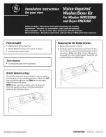
To produce steam, the dryer must connect to 

the cold water supply. Since the washer must 

also connect to the cold water, a “Y” connector 

is inserted to allow both inlet hoses to make that 

connection at the same time.

NOTE: 

Use the new inlet hoses provided; never use 

old hoses.

1

.  Turn the cold water faucet off. Remove the 

washer inlet hose from the washer fill valve 

connector (cold).

2

.  Ensure the rubber flat washer is in place and 

attach one female coupling of the short hose 

onto the washer fill valve connector. Tighten by 

hand until firmly seated.

3

.  Attach one male end of the “Y” connector to the 

other female coupling of the short hose. Ensure 
the rubber flat washer is in place. Tighten by 
hand until firmly seated.

4

.  Insert the filter screen in the coupling of the 

washer’s

 inlet hose. If a rubber flat washer is 

already in place remove it before installing the 

filter screen. Attach this coupling to one male end 

of the ‘’Y’’ connector. Tighten by hand until firmly 

seated.

5

.  Ensure the rubber flat washer is in place and 

attach the 

dryer’s

 long inlet hose to one male 

end of the ‘’Y’’ connector. Tighten by hand until 

firmly seated.

6

.  Ensure the rubber flat washer is in place and 

attach the other end of the 

dryer’s

 long inlet 

hose to the fill valve connector at the bottom of 

the dryer back panel. Tighten by hand until firmly 

seated.

4

Installation Instructions

CONNECTING INLET HOSES

7

.  Using pliers, tighten all the couplings with an 

additional two–thirds turn.

NOTE:

 Do not overtighten. Damage to the couplings 

may result.

8.

  Turn the water faucet on.

9

.  Check for leaks around the ‘’Y’’ connector, faucet 

and hose couplings.

WATER SUPPLY REQUIREMENTS

Hot and cold water faucets MUST be installed 

within 42 in. (107 cm) of your washer’s water 

inlet. The faucets MUST be 3/4 in. (1.9 cm) garden 

hose-type so inlet hoses can be connected. Water 

pressure MUST be between 10 and 120 pounds 

per square inch. Your water department can 

advise you of your water pressure.

NOTE:

 A water softener is recommended to reduce 

buildup of scale inside the steam generator if the 

home water supply is very hard.

CONNECTING INLET HOSES  

(on some models)

CONNECTING INLET HOSES  

(on some models) 

(cont.)

Summary of Contents for GTD75GCPLDG

Page 1: ...Appliances at 800 GE CARES 800 432 2737 or visit our Web site at GEAppliances com Fire Hazard WARNING Clothes dryer installation must be performed by a qualified installer Install the clothes dryer ac...

Page 2: ...essory WE25X20060 Complete Kit hoses Y adapter washers included OR WE1M847 Long Hose and WE01X22395 Short Hose PM14X10056 Dryer door opening vent brush not included WX14X10007 LintEater Dryer rotary t...

Page 3: ...or electrical connection information REQUIREMENTS FOR ALCOVE OR CLOSET INSTALLATION Explosion Hazard WARNING Keep flammable materials and vapors such as gasoline away from dryer Place dryer at least 1...

Page 4: ...the rubber flat washer is in place and attach the dryer s long inlet hose to one male end of the Y connector Tighten by hand until firmly seated 6 Ensure the rubber flat washer is in place and attach...

Page 5: ...F position Disconnect and discard old flexible gas connector and ducting material Shut off Valve MATERIALS YOU WILL NEED 10 Adjustable wrenches 2 8 Pipe wrench Flat blade screwdriver Level Slip joint...

Page 6: ...ordinances or in their absence the NATIONAL FUEL GAS CODE ANSI Z223 Explosion Hazard WARNING Use a new CSA International approved flexible gas supply line Never reuse old flexible connectors Install...

Page 7: ...SUPPLY cont Open the gas shut off valve F Apply pipe compound or PTFE tape to all male threads Shut Off Valve Plugged Tapping CONNECTING THE DRYER TO THE GAS SUPPLY Install a female 3 8 NPT elbow at t...

Page 8: ...receptacle Ensure proper ground exists before use GROUNDING INSTRUCTIONS This dryer must be grounded In the event of a malfunction or breakdown grounding will reduce the risk of electric shock by prov...

Page 9: ...FF THE TERMINAL BLOCK 9 MATERIALS YOU WILL NEED 4 dia metal elbow 3 4 Strain relief UL recognized 4 Duct clamps 2 or 4 spring clamps 2 Safety glasses 4 dia metal duct recommended 4 Cover plate Kit WE4...

Page 10: ...ailure to do so can result in death fire or electrical shock GROUNDING INSTRUCTIONS For a grounded cord connected dryer This dryer must be grounded In the event of a malfunction or breakdown grounding...

Page 11: ...at the electrical box 2 Be sure the dryer cord is unplugged from the wall receptacle 3 Remove the power cord cover located at the lower back 4 Remove and discard ground strap Keep the green ground scr...

Page 12: ...at comply with UL 2158A STANDARD FOR CLOTHES DRYER TRANSITION DUCT shall be used Avoid resting the duct on sharp objects For best drying performance 1 Slide one end of the duct over the clothes dryer...

Page 13: ...ill be treated like one 90 elbow For every additional 90 elbow reduce the allowable vent system length by 10 feet When calculating the total vent system length you must add all the straight portions a...

Page 14: ...nce to the exhaust airflow and should require little or no maintenance to prevent clogging Wall caps must be installed at least 12 above ground level or any other obstruction with the opening pointed...

Page 15: ...ab on the appliance base ADDING ELBOW AND DUCT FOR EXHAUST TO SIDE OF CABINET TAB LOCATION Fire Hazard WARNING Disconnect dryer from electrical supply Wear gloves and arm guards Close the back opening...

Page 16: ...ROUGH BOTTOM OF CABINET Insert the elbow through the rear opening and connect it to the dryer internal duct Apply duct tape as shown on the joint between the dryer internal duct and the elbow and also...

Page 17: ...rewdriver Tape tipped putty knife Small flat blade screwdriver Before you start Unplug the dryer from its electrical outlet Choose the REVERSING THE DOOR instructions A or B for your model A REVERSING...

Page 18: ...er left side screw holes and firmly tighten all 4 screws 6 Install the 4 plastic caps removed in step 1 into the 4 right side front panel holes NOTE To return the door to the original setup follow the...

Page 19: ...oles 2 on the left and 2 on the right 3 Loosen each top hinge screw on right side Remove the door and place it on a protective flat surface to avoid any damage Plastic Cap 4 Left side of front panel L...

Page 20: ...r back into its electrical outlet Door Hang door and tighten screws B REVERSING THE DOOR GLASS PANEL DOOR MODELS cont 6 Remove and swap the 2 plastic caps and the 2 hinges 7 Rotate the outer door 180...

Page 21: ...i tiene alguna pregunta llame GE Appliances a 800 GE CARES 800 432 2737 o visite nuestro sitio Web en GEAppliances com ADVERTENCIA Riesgo de incendio La instalaci n de la secadora debe efectuarla un i...

Page 22: ...no incluido WX14X10007 Cepillo con tuber a giratoria LintEater no incluido DIMENSIONES APROXIMADAS Incline la secadora de costado y saque los pa os de espuma de embalaje tirando de los costados y quit...

Page 23: ...Los espacios libres m nimos respecto de superficies combustibles y de aberturas de aire son 0 a ambos lados 1 2 54 cm en la parte trasera 1 2 54 cm en la parte superior Se deber considerar que se deb...

Page 24: ...en su lugar y sujete la manguera larga de entrada de la secadora a un extremo macho del conector en Y Ajuste a mano hasta que est firmemente asentada 6 Aseg rese de que la arandela plana de goma se e...

Page 25: ...ible de gas y el material del conducto V lvula de cierre HERRAMIENTAS NECESARIAS MATERIALES NECESARIOS Llaves ajustables de 10 2 Llave para tubos de 8 Destornillador de lados planos Nivel Pinzas Codo...

Page 26: ...nternational Nunca vuelva a usar conectores flexibles viejos Instale una v lvula de cierre manual individual dentro de 6 pies de la secadora en acuerdo con el C digo Nacional de Gas Combustible ANSI Z...

Page 27: ...compuesto para tuber a o cinta PTFE en todas las roscas macho V lvula de apagado Toma a rosca C MO CONECTAR LA SECADORA AL SUMINISTRO DE GAS Instale un codo hembra NPT de 3 8 al final de la entrada de...

Page 28: ...descarga el ctrica Circuito individual correctamente polarizado y conectado a tierra interruptor de 15 o 20 amperios o un fusible de retardo Potencia 2 hilos m s la tierra 120 voltios monof sica 60 Hz...

Page 29: ...ALES NECESARIOS Codo de metal de 4 de di metro Alivio de tensi n de 3 4 reconocido por UL Abrazaderas de tuber a de 4 2 o abrazaderas de resorte de 4 2 Gafas de seguridad Conducto de metal de 4 de di...

Page 30: ...producir la muerte incendio o descarga el ctrica INSTRUCCIONES DE CONEXI N A TIERRA Para una secadora conectada con cable con conexi n a tierra Esta secadora deber estar conectado a tierra En caso de...

Page 31: ...te el fusible del circuito de la secadora de la caja el ctrica 2 Verifique que el cable de la secadora est desenchufado del tomacorriente 3 Quite la tapa del cable de energ a ubicada en la parte trase...

Page 32: ...ite que la tuber a se apoye sobre objetos cortantes Para un mejor funcionamiento 1 Deslice un extreme del conducto sobre la tuber a de salida de la secadora de ropa 2 Asegure el conducto con una abraz...

Page 33: ...codos de 45 deber n ser considerados como un codo de 90 Para cada codo adicional de 90 reduzca en 10 pies la longitud permisible del sistema de escape En el c lculo de la longitud total del sistema de...

Page 34: ...be requerir poco mantenimiento para evitar las obstrucciones Las cubiertas de pared deben instalarse por lo menos a 12 sobre el nivel del suelo o cualquier otra obstrucci n con la abertura apuntando h...

Page 35: ...gar a trav s de la leng eta de la base del artefacto C MO AGREGAR CODOS Y CONDUCTOS DE SALIDA HACIA DEL GABINETE Corte el conducto como puede verse y conserve la porci n A Para los modelos GTD60 GTD65...

Page 36: ...onducto interno de la secadora Aplique cinta aislante como puede verse en la junta entre el conducto interno de la secadora y el codo y tambi n en la junta entre el codo y el conducto inferior Las jun...

Page 37: ...ta cubierta con cinta Destornillador de punta plana peque a Antes de Comenzar Desenchufe la secadora del tomacorriente A INVERSI N DE LA PUERTA MODELOS DE PUERTA S LIDA 1 Abra la puerta aproximadament...

Page 38: ...izquierdo y apriete firmemente los cuatro tornillos 6 Instale las cuatro tapas de pl stico retiradas en el paso 1 en los 4 agujeros del panel frontal derecho NOTA Para regresar la puerta a la configu...

Page 39: ...opuestas Tapa de pl stico 4 Lado izquierdo del panel frontal Placa ciega Placa de refuerzo 3 Afloje cada tornillo de la bisagra superior en el lado derecho Retire la puerta y coloque la misma sobre un...

Page 40: ...a enchufar la secadora en la salida el ctrica Puerta Sostenga la puerta y ajuste los tornillos Tapa de pl stico 4 Lado derecho del panel frontal B INVERSI N DE LA PUERTA MODELOS CON PANEL DE CRISTAL...

Reviews: