background image

– 9 –

Compacting

To start the compactor:

1.    Turn the knob to ON.

2.    Make sure the drawer is fully closed.

3.    Lift the foot pedal up to start cycle.

The ram travels downward into the drawer, 

compacting the trash. At the bottom of the stroke, 

the ram automatically reverses direction, retracts 

from the drawer, returns to its starting position, and 

the compactor shuts off automatically.

The cycle takes less than 30 seconds. As the trash 

drawer fills with trash, cycle time gets progressively 

shorter.

WARNING:

 When bottles and cans are compacted, 

small tears in the bag may occur. This is normal 

and in no way affects the performance of the 

compactor. Keep the bag away from your body to 

prevent injury from sharp objects that may have 

pierced the bag.

Caution: 

Do not apply too much force when turning 

the knob. The knob should always rotate easily. 

Forcing may break the knob and damage the 

switch.

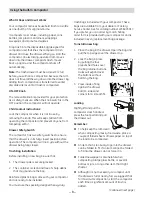
When emptying waste baskets into the trash 

drawer, some items may spill into the compactor 

behind the drawer. Items behind the drawer could 

prevent it from closing completely and prevent 

the compactor from operating. To remove such 

items from behind the drawer, open the drawer 

and remove it to clean them out. See the Care and 

Cleaning section.

Notes:

  You will not see compacting of trash the first 

few times you load. The compactor drawer should 

be about 1/2 full before the compactor can begin to 

compress the load.
Glass bottles can make a loud noise when they 

break during compaction. This is normal. Also, 

bottles in the trash drawer will not always break 

during the first cycle. Breaking glass and associated 

noise may occur several cycles later, depending on 

the type and volume of the trash.

To stop the compactor: 

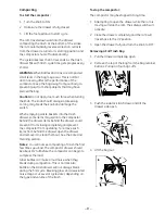
The compactor may be stopped at any time.

1.    Attempting to open the drawer while the ram is 

moving will stop the ram. The safety switch will 

activate.

2.    Close the drawer completely and the ram will 

travel back to the UP position.

3.    Open the drawer fully and turn the knob to OFF. 

Removing a Full Trash Bag

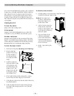
1.    Pull the drawer completely open.

2.    Remove the top of the bag from the bag retainer 

buttons. Pull up all four bag cuffs.

3.    Push the side-lock latch down and tilt the 

drawer side open.

4.    Lift the bag out.


Summary of Contents for GCG1500 WW

Page 1: ...BB GCG1500WW GCG1580SS GCG1700II ZCGS150SS ZCGP150II GE Appliances General Electric Company Louisville Kentucky 40225 31 9143 15 in Built In Compactors Technical Service Guide JULY 2006 GE Consumer Industrial ...

Page 2: ... avoid personal injury disconnect power before servicing this product If electrical power is required for diagnosis or test purposes disconnect the power immediately after performing the necessary checks RECONNECT ALL GROUNDING DEVICES If grounding wires screws straps clips nuts or washers used to complete a path to ground are removed for service they must be returned to their original position an...

Page 3: ...eatures 7 Diagnostics and Service Information 23 Directional Switch 14 Features 4 Installation Requirements 5 Motor Assembly 17 Nomenclature 6 ON OFF Switch 14 Power Screw Assembly 21 Ram Assembly 19 Schematic 25 Start Switch 15 Switch Bracket 13 Tilt Switch 15 Tilt Switch Drawer 16 Top Cover Panel 16 Top Limit Switch 14 Using the Built In Compactor 8 Warranty 26 ...

Page 4: ...ustom Panels Required Color Appearance Code II SS BB WW SS II Door Control Panel Color SS Toe Kick Black and Stainless Steel Black and Stainless Steel Black and Stainless Steel Black and Stainless Steel Black and Stainless Steel 3 4 Panel Capability Yes No No No Yes WEIGHTS DIMENSIONS Approximate Shipping Weight 144 lb 144 lb 144 lb 144 lb 144 lb Cabinet Width 15 1 8 in 15 1 8 in 15 in 15 in 15 in...

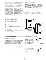
Page 5: ...cle The outlet box should be located within reach of the 36 in power cord This appliance must be supplied with 120V 60Hz and connected to an individual properly grounded branch circuit protected by a 15 or 20 ampere circuit breaker or time delay fuse 33 3 4 min to 35 max 14 7 8 23 34 to 35 15 1 8 min 24 min Locate the outlet 18 min from the floor 3 min from either side The fully integrated design ...

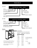
Page 6: ...G APR 2003 F H MAY 2002 D L JUN 2001 A M JUL 2000 Z R AUG 1999 V S SEP 1998 T T OCT 1997 S V NOV 1996 R Z DEC 1995 M Nomenclature Mini Manual Width 150 15 inch Z C G S 1 5 0 L S S Brand Z Monogram Product Type CG Built In Compactor Exterior Color SS Stainless Steel II Requires Custom Cabinetry Panel Model Year Designator Door S Stainless P Panel Model Designator Designates features the higher the ...

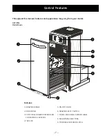
Page 7: ...ur model Control Features Features 1 DRAWER HANDLE 2 DOOR PANEL 3 FOOT PEDAL DRAWER OPENER AND COMPACTOR ACTIVATION 4 TOE KICK 5 ON OFF KNOB 6 DRAWER SAFETY SWITCH 7 MODEL AND SERIAL NUMBER LABEL 8 BAG RETAINER BUTTONS 9 MOVEABLE SIDE DOOR LATCH GE Profile Model Shown ...

Page 8: ...s securely locked 2 The container is clean and free of sharp debris that may puncture the bag Reinforced plastic bags came with your compactor and are ready to be installed You must use the specially designed heavy duty trash bags included with your compactor These bags are available from your dealer or Factory Service Center Ask for catalog number WC60X5017 If you prefer you can order by mail A h...

Page 9: ...hind the drawer could prevent it from closing completely and prevent the compactor from operating To remove such items from behind the drawer open the drawer and remove it to clean them out See the Care and Cleaning section Notes You will not see compacting of trash the first few times you load The compactor drawer should be about 1 2 full before the compactor can begin to compress the load Glass b...

Page 10: ...ay be bits of glass in the drawer Press the side door latch down 3 Hold the side door latch and tilt the side of the drawer until the latch clears the drawer front The drawer side can be removed by tilting and sliding it out 4 Wash with a damp cloth using warm soapy water Rinse and then dry with a soft cloth 5 If the drawer side was removed slide it back into the tilted position 6 Press the side d...

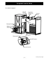
Page 11: ... 11 15 in Built In Compactor Component Locator Views Continued next page ...

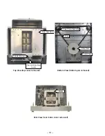
Page 12: ...op View top cover removed Bottom View bottom pan removed Rear View rear motor cover removed Actuator Bracket Shaft Plate Power Screw Assembly Ram Assembly Drive Gear Motor Chain Top Limit Directional Switch ...

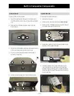
Page 13: ...tach the switch bracket to the frame 1 2 3 Insert a small bladed screwdriver between the top of the control panel and the front cover Pry the control panel forward and release it from the 3 top tabs 3 4 Lift the control panel from the 3 bottom tabs 5 Raise the switch wiring harness parallel to the bottom of the switch bracket 4 Pull the bottom of the switch bracket out to clear the bottom of the f...

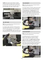
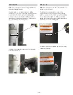
Page 14: ...rectional switch See Switch Bracket and ON OFF Switch The directional switch is positioned on the left side of the top limit switch closest to the ON OFF switch It is connected with blue yellow and red wires Both switches are attached to the inside of the switch bracket with 2 Phillips head screws Caution Ensure the switch bracket is installed with the switch arms resting in front of the switch ac...

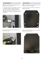
Page 15: ... release the locking tabs Tilt Switch Note Disconnect power to the compactor before accessing the tilt switch The tilt switch is located in the front of the compactor above the drawer opening The tilt switch is secured in the front cover with a locking tab located on the right side of the switch It is necessary to use a small flat blade screwdriver to press and release the locking tab The switch ca...

Page 16: ... the bottom of the switch It is necessary to use a small flat blade screwdriver to press and release the locking tab The switch can then be pulled out and the 2 wire leads disconnected Tilt Switch Drawer Top Cover Panel Note To access the top cover panel the compactor must be removed from installation The top cover panel is attached to the frame with 6 Phillips head screws After removal of the 6 sc...

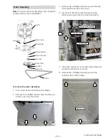
Page 17: ...tor Wire Harness Neutral Wire Track Shield Place the compactor on a protected surface and stand the compactor on its top Remove the 3 Phillips head screws and the bottom pan from the frame 5 6 Bottom Pan Continued next page To remove the motor assembly Disconnect power and remove the drawer Remove the 3 Phillips head screws and the rear motor cover from the frame 1 2 Motor Motor Gear Gear Pin Ring...

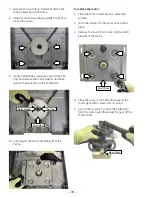
Page 18: ...fully lift the motor assembly from the frame 10 Metal Washer Clip Ring Drive Gear Place the motor on it s side and support the motor gear with a piece of in wood Use a 3 16 in punch to drive the slotted pin from the motor gear then slide the gear off the motor shaft 4 5 Shaft Plate Motor Gear To replace the motor Place the motor assembly on a protected surface Mark the position of the motor on the...

Page 19: ...position approximately flush with top of frame A repetitive thumping sound will be heard 3 4 in Recess Flush Ram Assembly Frame Frame Ram Assembly Disconnect power Remove the switch bracket See Switch Bracket Lift and remove the ram assembly from the top of the power screws 5 6 7 Actuator Bracket Switch Arms Continued next page To replace the ram assembly Note Be sure to position the actuator brack...

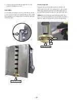
Page 20: ... the bottom of each side of the ram It is necessary to use a small flat blade screwdriver to remove the retaining clip and pin that hold each power screw nut to the ram Caution Discard the removed retaining clips and pins Use the new retaining clips and pins included with the replacement power screw nut assembly Power Screw Nut Pin Clip Tab Slide Power Screw Nut Connect power and check operation of...

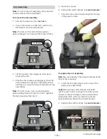
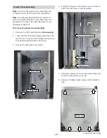
Page 21: ...he ram assembly See Ram Assembly Lower the left front leveling leg and remove the two 11 32 in nuts and the Phillips head screws that hold the frame slide to the frame Remove the left side screw shield 1 2 3 Frame Slide Screw Shield Pull up the stopper and stopper cap and remove both from the power screw assembly 4 Place the compactor on a protected surface and stand the compactor on its top Remov...

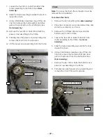
Page 22: ... the chain the compactor must be removed from installation To remove the chain Remove the ram assembly See Ram Assembly Place the compactor on a protected surface and stand the compactor on it s top Remove the 5 Phillips head screws and the bottom pan from the frame Loosen the four 3 8 in bolts that attach the motor assembly to the frame See Motor Assembly Slide the motor assembly towards the fron...

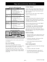
Page 23: ...ch contacts Motor Run Winding 1 Remove the blue wire from the start switch and the blue wires from the top limit switch and the directional switch 2 Connect an ohmmeter to the blue wire and to the neutral side of the power cord 3 An accurate ohmmeter should read about 1 2 1 6 ohms Motor Centrifugal Switch 1 Disconnect the wires from the motor centrifugal switch 2 Connect an ohmmeter to terminals 3...

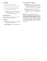
Page 24: ... WC01X10006 oil Not Compacting Complaints Low Voltage Check supply voltage with the ram compacting trash At 120 volts ram force is approximately 2300 lbs At voltage lower than 120 volts ram force is reduced Ram Travel Ram stops 7 1 2 190mm above bottom of container No noticeable compaction will occur until container is 1 2 full Note For best compacting results do not overload the compactor contain...

Page 25: ...n closes the tilt switch drawer and tilt switch The directional switch is closed for down travel Blue to Yellow and the top limit switch is open The consumer starts the cycle by closing the foot pedal start switch The motor starts in down travel The motor centrifugal switch opens immediately when the motor runs After the first inch of down travel the top limit switch closes and the directional swit...

Page 26: ... 26 Warranty ...

Reviews:

Related manuals for GCG1500 WW