– 25 –
WARNING:
Disconnect electrical power before servicing.
Caution
: Label all wires prior to disconnection. Wiring errors can cause improper and dangerous operation.
Verify operation after servicing.
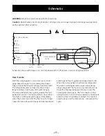
Schematic
N
L1
TILT SWITCH (DRA WER)
BLACK
TILT
SWITCH
ORANGE
ON-OFF
SWITCH
COM
NO
START
SWITCH
BROWN
C
NC 2 NO 2
NC 2
OM 1
BLUE
TOP L IMIT
SWITCH
DIRECTIONAL
SWITCH
MOTOR CENTRIFUGAL
SWITCH
COM1
BLUE
CW START
CCW START
RUN
MOTOR
PROTECTOR
YELLOW
RED
Schematic shown with drawer out, control panel switch in off position, and ram at up travel limit.
How it works:
With the unit plugged in, consumer turns control
panel (ON-OFF) switch to ON. Sliding the drawer
fully in closes the tilt switch (drawer) and tilt switch.
The directional switch is closed for down travel
(Blue to Yellow), and the top limit switch is open.
The consumer starts the cycle by closing the foot
pedal start switch. The motor starts in down travel.
The motor centrifugal switch opens immediately
when the motor runs. After the first ¾ inch of down
travel, the top limit switch closes and the directional
switch opens blue to yellow and closes blue to red.
When the ram reaches a mechanical stall position,
the motor centrifugal switch closes (run winding
stays energized). The motor is now restarted for up
travel thru the directional switch blue to red. The
centrifugal switch opens. The ram travels up and,
during the last ¾ inch of travel, resets the directional
switch to down travel (Blue to Yellow). The top limit
switch opens and the motor stops - completing the
cycle.

