


30
GE INFORMATION
G500 SUBSTATION GATEWAY INSTRUCTION MANUAL
CHAPTER 3: INSTALLING THE G500
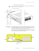
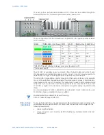
through P16 are connected to the second G500. Connections from the switch panel to
both G500 units should be made in the same order. For example, if P2 is connected to
port 3 on the first G500, P10 should also be connected to port 3 on the second G500.
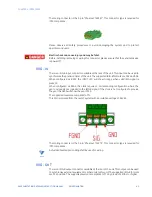
10. Connect field devices to J2 through J8 on the first RS232 switch panel and to J1
through J8 on the second panel.
RS232 switch panel
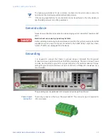
The RS232 switch panel has two sets of indicator LEDS:
•
PWR A/PWR B: When lit, power and communications are received from the connected
units. Normally, both LEDs are lit.
•
CCU A/CCU B: Normally, one LED is lit, indicating which unit is active.
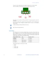
The active/standby switch on the front of the RS232 switch panel is used to:
•
Restore a previously failed unit to active status once it has been repaired.
•
Manually force a unit to active status so that routine maintenance can be performed
on the other unit.
To manually operate
the RS232 switch
panel:
1.
Pull the active/standby switch straight out to release it from the locked position
2.
Switch it up to make unit A active or down to make unit B active
The CCU A/CCU B LED indicator indicates which unit has been activated.
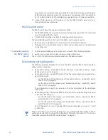
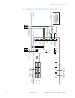
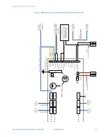
Redundancy wiring diagrams
The following diagrams illustrate how to wire the G500 units and RS232 switch panels to
enable system redundancy:
•
Redundancy Wiring - Single RS232 Switch Panel see “Redundancy Wiring - Single
RS232 Switch Panel” on page 31.
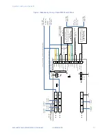
•
Redundancy Wiring - Dual RS232 Switch Panel. The wiring drawing is provided in two
parts: left and right.
–
For the left side of the drawing, see “Redundancy Wiring - Dual RS232 Switch
Panel (1 of 2)” on page 32.
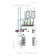
–
For the right side of the drawing, see “Redundancy Wiring - Dual RS232 Switch
Panel (2 of 2)” on page 33.
This configuration is used to provide up to 15 serial connections to the redundant
G500 units.
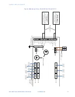
•
Redundancy Wiring - Redundant RS232 Switch Panel. The wiring drawing is provided
in two parts: left and right.
–
For the left side of the drawing, see “Redundancy Wiring - Redundant RS232
Switch Panel (1 of 2)” on page 34.
–
For the left side of the drawing, see “Redundancy Wiring - Redundant RS232
Switch Panel (2 of 2)” on page 35.
This configuration is used to provide RS232 panel redundancy for up to 7 serial
connections.
NOTE
When connecting to more than 8 field devices, you must double the number of RS232
switch panels used. When using this configuration, follow the instructions in “To set up a
redundant system with two RS232 switch panels:” on page 29.
Summary of Contents for G500
Page 6: ...6 GE INFORMATION G500 SUBSTATION GATEWAY INSTRUCTION MANUAL TABLE OF CONTENTS ...
Page 16: ...16 GE INFORMATION G500 SUBSTATION GATEWAY INSTRUCTION MANUAL CHAPTER 1 INTRODUCTION ...
Page 36: ...36 GE INFORMATION G500 SUBSTATION GATEWAY INSTRUCTION MANUAL CHAPTER 3 INSTALLING THE G500 ...
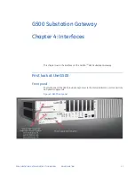
Page 64: ...64 GE INFORMATION G500 SUBSTATION GATEWAY INSTRUCTION MANUAL CHAPTER 4 INTERFACES ...
Page 72: ...72 GE INFORMATION G500 SUBSTATION GATEWAY INSTRUCTION MANUAL CHAPTER 5 INDICATORS ...
Page 77: ...CHAPTER 6 SPECIFICATIONS G500 SUBSTATION GATEWAY INSTRUCTION MANUAL GE INFORMATION 77 ...
Page 78: ...78 GE INFORMATION G500 SUBSTATION GATEWAY INSTRUCTION MANUAL CHAPTER 6 SPECIFICATIONS ...
Page 80: ...80 GE INFORMATION G500 SUBSTATION GATEWAY INSTRUCTION MANUAL CHAPTER 6 SPECIFICATIONS ...
Page 86: ...86 GE INFORMATION G500 SUBSTATION GATEWAY INSTRUCTION MANUAL APPENDIX B CUL ...
Page 88: ...88 GE INFORMATION G500 SUBSTATION GATEWAY INSTRUCTION MANUAL APPENDIX C WARRANTY ...
Page 92: ...92 GE INFORMATION G500 SUBSTATION GATEWAY INSTRUCTION MANUAL REVISION HISTORY ...


