


18
GE INFORMATION
G500 SUBSTATION GATEWAY INSTRUCTION MANUAL
CHAPTER 2: UNPACKING AND INSPECTION
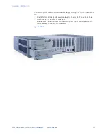
Only after ensuring that both you and the surrounding area are protected from ESD,
carefully remove the board or module from the shipping carton by grasping the module on
its edges. Place the board, in its anti-static bag, flat down on a suitable surface. You may
then remove the board from the anti-static bag by tearing the ESD warning labels.
Initial inspection
After unpacking the products, you should inspect it for visible damage that could have
occurred during shipping or unpacking. If damage is observed (usually in the form of bent
component leads or loose socketed components), contact GE Technical Support for
additional instructions. Depending on the severity of the damage, it may be necessary to
return the product to the factory for repair.
DO NOT apply power to the board if it has visible damage!
Doing so may cause further, possibly irreparable damage, as well as introduce a fire or
shock hazard.
Unpacking
Please read the manual carefully before unpacking the board or module or fitting the
device into your system. Also adhere to the following:
•
Observe all precautions for electrostatic sensitive modules
•
Do not place the board on conductive surfaces, anti-static plastic, or sponge, which
can cause shocks and lead to board trace damage.
•
Do not exceed the specified operational temperatures.
•
Keep all original packaging material for future storage or warranty shipments of the
board.
Although the products are carefully packaged to protect against the rigors of shipping, it is
still possible that shipping damage can occur. Careful inspection of the shipping carton
should reveal some information about how the package was handled by the shipping
service. If evidence of damage or rough handling is found, you should notify the shipping
service and GE Technical Support as soon as possible.
NOTE
PCIe Cards and storage devices may also have temperature restrictions
Retain all packing material in case of future need.
Before installing or removing any board, please ensure that the system power and
external supplies have been turned off!
Summary of Contents for G500
Page 6: ...6 GE INFORMATION G500 SUBSTATION GATEWAY INSTRUCTION MANUAL TABLE OF CONTENTS ...
Page 16: ...16 GE INFORMATION G500 SUBSTATION GATEWAY INSTRUCTION MANUAL CHAPTER 1 INTRODUCTION ...
Page 36: ...36 GE INFORMATION G500 SUBSTATION GATEWAY INSTRUCTION MANUAL CHAPTER 3 INSTALLING THE G500 ...
Page 64: ...64 GE INFORMATION G500 SUBSTATION GATEWAY INSTRUCTION MANUAL CHAPTER 4 INTERFACES ...
Page 72: ...72 GE INFORMATION G500 SUBSTATION GATEWAY INSTRUCTION MANUAL CHAPTER 5 INDICATORS ...
Page 77: ...CHAPTER 6 SPECIFICATIONS G500 SUBSTATION GATEWAY INSTRUCTION MANUAL GE INFORMATION 77 ...
Page 78: ...78 GE INFORMATION G500 SUBSTATION GATEWAY INSTRUCTION MANUAL CHAPTER 6 SPECIFICATIONS ...
Page 80: ...80 GE INFORMATION G500 SUBSTATION GATEWAY INSTRUCTION MANUAL CHAPTER 6 SPECIFICATIONS ...
Page 86: ...86 GE INFORMATION G500 SUBSTATION GATEWAY INSTRUCTION MANUAL APPENDIX B CUL ...
Page 88: ...88 GE INFORMATION G500 SUBSTATION GATEWAY INSTRUCTION MANUAL APPENDIX C WARRANTY ...
Page 92: ...92 GE INFORMATION G500 SUBSTATION GATEWAY INSTRUCTION MANUAL REVISION HISTORY ...


