


CHAPTER 3: INSTALLING THE G500
G500 SUBSTATION GATEWAY INSTRUCTION MANUAL
GE INFORMATION
25
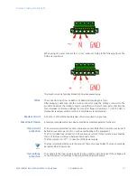
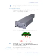
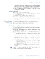
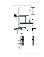
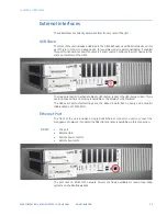
When using DC power, connect the “+”and “- wires according to the following figure. The
GND wire is optional.
The inrush current is typically limited to 35A when powering up.
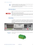
Wires
The conductor size is from 16 AWG to 12 AWG and strip length is 7mm.
After plugging cable lines into the mating connector, plug the mating connector to the
product and secure the mating connector using the two screws. For proper connection, the
recommended tool torque settings for connector flange screws are 2.7 in-lb [0.3 Nm]. A
Flathead screwdriver with 0.4 mm by 2.5 mm blade is recommended.
Breaker Circuit
A 16A IEC or 20A USA/Canada breaker circuit is required as a pre-fuse.
Disconnect Device
A readily accessible disconnect device shall be incorporated external to the unit.
Overcurrent
protection
The overcurrent protection function interrupts an uncontrolled fault current or overcurrent
before serious damage can occur, such as overheating of the equipment.
The PSU included fuse is rated for 6.3A continuous current. If that current is exceeded by
factor 10 the fuse will blow in between 10ms and 100ms.
The fuse is placed in “N”/ ”-“ connection of the power supply.
NOTE
The fuse is soldered directly onto the product. There is no fuse holder. The fuse should only
be replaced by GE personnel.
Overvoltage
protection
The voltage to the inner loads is protected by a varistor. High increase of the voltage will
cause the internal current fuse to blow and/or the Varistor to break.
Summary of Contents for G500
Page 6: ...6 GE INFORMATION G500 SUBSTATION GATEWAY INSTRUCTION MANUAL TABLE OF CONTENTS ...
Page 16: ...16 GE INFORMATION G500 SUBSTATION GATEWAY INSTRUCTION MANUAL CHAPTER 1 INTRODUCTION ...
Page 36: ...36 GE INFORMATION G500 SUBSTATION GATEWAY INSTRUCTION MANUAL CHAPTER 3 INSTALLING THE G500 ...
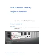
Page 64: ...64 GE INFORMATION G500 SUBSTATION GATEWAY INSTRUCTION MANUAL CHAPTER 4 INTERFACES ...
Page 72: ...72 GE INFORMATION G500 SUBSTATION GATEWAY INSTRUCTION MANUAL CHAPTER 5 INDICATORS ...
Page 77: ...CHAPTER 6 SPECIFICATIONS G500 SUBSTATION GATEWAY INSTRUCTION MANUAL GE INFORMATION 77 ...
Page 78: ...78 GE INFORMATION G500 SUBSTATION GATEWAY INSTRUCTION MANUAL CHAPTER 6 SPECIFICATIONS ...
Page 80: ...80 GE INFORMATION G500 SUBSTATION GATEWAY INSTRUCTION MANUAL CHAPTER 6 SPECIFICATIONS ...
Page 86: ...86 GE INFORMATION G500 SUBSTATION GATEWAY INSTRUCTION MANUAL APPENDIX B CUL ...
Page 88: ...88 GE INFORMATION G500 SUBSTATION GATEWAY INSTRUCTION MANUAL APPENDIX C WARRANTY ...
Page 92: ...92 GE INFORMATION G500 SUBSTATION GATEWAY INSTRUCTION MANUAL REVISION HISTORY ...