


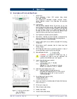


4.5.5 LP-11 series: 2 / 3 / 4 parallel operating units – additional info
The RPA option (Redundant Parallel Architecture) allows you to create a redundant UPS system in which 2, 3
or 4
LP
units operate in parallel. The following should be considered when installing units in parallel.
This section gives additional information on:
- installation (4.5.5.1)
- start-up (4.5.5.2)
- use / maintenance (4.5.5.3)
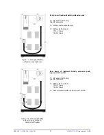
4.5.5.1 Notes concerning installation of a parallel system
1.
All inputs of the UPSs must be supplied from the same phase. This is to enable bypass operation of the
parallel system. All inputs must be individually protected by fuses in the installation. The values of these
fuses should correspond to the values mentioned in section 4.5 table 1.
2.
All outputs must be connected together, supplying the load. It is advised to install switches (S 1-4,
fig. 10) in the output wiring, in order to be able to isolate a unit from the remaining system for service and
maintenance purposes. It is advised to make a Neutral-to-Ground bounding in the output junction.
3.
The diameter of input and output cables must be according to the table in the installation drawings (see
appendix). Cables with different diameters can cause tripping fuses in the UPS and/or the installation.
4.
The length of all input cables from the input junction (Li, fig. 10) to the UPS inputs should be equal.
The same applies to the cables from the outputs to the output junction (Lo, fig. 10). The minimum length of
the input as well as the output cables is 3 meters.
RPA CARD
LP-UPS
OUT
IN
RPA CARD
LP-UPS
OUT
IN
RPA CARD
LP-UPS
OUT
IN
RPA CARD
LP-UPS
OUT
IN
1-PHASE 3-WIRE INPUT
INPUT JUNCTION
BUS
TERMINATOR
YELLOW NETWORK
CABLES AS DELIVERED
WITH THE UPS
OUTPUT JUNCTION
Li/Lo: LENGTH OF I/O WIRING
- EQUAL FOR EACH UPS
- MINIMUM 3 METERS
S 1-4
SWITCH ALLOWS
ISOLATION OF A UNIT
FROM THE SYSTEM
BUS
TERMINATOR
F 1-4
DISTRIBUTION
FUSE VALUES
ACCORDING TO
TABLE 1
TO LOAD
Figure 10. Installation of parallel operating LP 11 UPSs
OPM_LPE_11X_3K0_10K_1GB_V041
13
GE DE LP 11 UPS: User manual 4.1 (GB)


