background image

February 2009

1-10

Diagnostics

Testing the Watchdog 

Timer Circuit

The CTF878 includes a watchdog timer circuit. If a software error 
causes the meter to stop responding, this circuit automatically resets 
the meter. A properly functioning CTF878 restarts if you run the 
Watchdog Test.

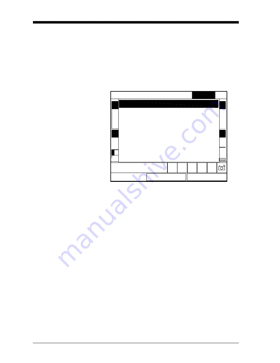
To start the Watchdog Test, scroll to the Watchdog Test option in the 
Test Menu and press 

[ENTER]

. The screen appears similar to 

Figure 1-8 below.

Figure 1-8: Watchdog Test Screen

Press 

[F2]

 (No) to cancel the test and return to the Menu screen, or 

press 

[F3]

 (Yes) to start the test. The CTF878 should go blank for a 

few seconds, and then restart. If it does not follow this sequence, 
consult the factory.

Units

Site    Program    Meter    Logging

*** WARNING ***

This test should automatically 

restart your meter!

Press "Yes" to start the test.
Press "No" to cancel the test.

No

Yes

Service

Watchdog Test

Summary of Contents for CTF878

Page 1: ...GE Sensing Model CTF878 Clamp On Tag Flowmeter User s Service Manual ...

Page 2: ...GE Sensing Model CTF878 Clamp On Tag Flowmeter User s Service Manual 910 254SA4 February 2009 ...

Page 3: ...rising from course of dealing or usage or trade Return Policy If a GE Sensing Inc instrument malfunctions within the warranty period the following procedure must be completed 1 Notify GE Sensing Inc giving full details of the problem and provide the model number and serial number of the instrument If the nature of the problem indicates the need for factory service GE Infrastructure Sensing Inc wil...

Page 4: ... Parameters 2 2 Updating CTF878 Software 2 3 Preparation 2 4 Setting Up the PC 2 5 Installing New Software 2 7 Completion 2 10 Chapter 3 Calibration Introduction 3 1 Entering the Calibration Test Menu 3 1 Testing and Calibrating Analog Outputs 3 2 Testing Analog Outputs 3 2 Calibrating Analog Outputs 3 2 Testing and Calibrating Analog Inputs 3 4 Testing Analog Inputs 3 4 Calibrating Analog Inputs ...

Page 5: ...d Problems 4 4 Gas Problems 4 4 Pipe Problems 4 5 Transducer Problems 4 6 Chapter 5 Parts Replacement Introduction 5 1 Replacing the Fuse 5 2 Removing the Printed Circuit Board 5 3 Installing an Option Card 5 4 Installing the Printed Circuit Board 5 5 Replacing the LCD Display 5 7 Spare Parts 5 8 Appendix A Service Record Introduction A 1 Data Entry A 1 ...

Page 6: ...Chapter 1 ...

Page 7: ...Diagnostics Introduction 1 1 Entering the Service Menu 1 1 Displaying Diagnostic Parameters 1 2 Signal Setup 1 3 Setting Error Limits 1 5 The Test Option 1 7 ...

Page 8: ...the screen Press the X arrow key to scroll from the Site Menu to the Service Menu At the Service Menu press ENTER The screen appears similar to Figure 1 1 below Figure 1 1 Service Menu To scroll to a particular option press the T or S arrow keys until you reach the option Then press ENTER to open the option window When entering parameters in an option press the T key to step through the available ...

Page 9: ...tics entry on the Service Menu and press ENTER The screen appears similar to Figure 1 2 below Figure 1 2 Diagnostics Tests Window Press F2 Cancel or F3 OK to close the window and return to Operate Mode Note For an explanation of diagnostic parameters refer to Chapter 4 Troubleshooting OK Cancel Meter Error 0x0004 Carr A Carr G I A Q A Mod G TAU Corr SNR Up 1000 9 72 390 680 3 13 19 25 34 4 65 992 ...

Page 10: ...lar to Figure 1 3 below Figure 1 3 Signal Parameter Window Setting Up Signal Parameters 1 Press the T arrow key to enter the window 2 The first prompt allows you to select or not select Reverse Flow a Press ENTER to select Reverse Flow and press the T arrow key to enter the next prompt or b Press ENTER again to deselect Reverse Flow and press the T arrow key to enter the next prompt AgcMgc CCorr A...

Page 11: ...ur selection d Press the T arrow key to enter the next prompt 5 The final prompt Errors Allowed specifies the number of errors the meter can record before displaying an error message The default is 2 a Press ENTER to open the text box b Use the numeric keys to enter the desired value c Press ENTER to confirm your entry You have finished entering data in the Signal Parameter window To leave this wi...

Page 12: ...alue is 10 The E8 SNR error message appears if the SNR falls below the limit programmed here IMPORTANT SNR Min should be changed from factory default settings only if absolutely necessary These settings may be changed by qualified field service engineers only To enter the minimum SNR a Press ENTER to open the text box b Use the numeric keys to enter the desired value c Press ENTER to confirm your ...

Page 13: ...h measurements the F1 softkey displays Metric Press F1 to display the measurement in the alternate format 4 The last four prompts ask for the minimum and maximum values in millivolts for the Carrier and DMod categories IMPORTANT Carrier and DMod should be changed from factory default settings only if absolutely necessary These settings may be changed by qualified field service engineers only To ch...

Page 14: ...st To enter this option scroll to the Test entry on the Service Menu and press ENTER The screen appears similar to Figure 1 5 below Figure 1 5 Test Option under Service Menu Scroll to the desired entry in the option menu and press ENTER Units Test Diagnostics Site Program Meter Logging Signal Setup Error Limits Test Keys Watchdog Test 34 0 50 100 19 25 Service TAU ms Test Test Screen Corr SNR ...

Page 15: ...you press a key a screen with a checkerboard pattern appears as in Figure 1 6 below Figure 1 6 A Functioning Test Screen Pressing a key two more times should result in two more checkerboard patterns followed by a series of dark and light screens Pressing the key through this sequence should return the CTF878 to Operate Mode If the test does not proceed according to this sequence please consult the...

Page 16: ...option on the Test Menu and press ENTER The screen appears similar to Figure 1 7 below Press any key on the keypad and a cell representing that key should darken Figure 1 7 The Test Keys Window Pressing the F3 key returns the meter to the Operate Mode If any key does not appear on the screen contact the factory Exit 7 4 1 5 0 8 2 6 9 3 MENU ESC SEL F1 F2 F3 Test Keys ...

Page 17: ...Watchdog Test option in the Test Menu and press ENTER The screen appears similar to Figure 1 8 below Figure 1 8 Watchdog Test Screen Press F2 No to cancel the test and return to the Menu screen or press F3 Yes to start the test The CTF878 should go blank for a few seconds and then restart If it does not follow this sequence consult the factory Units Site Program Meter Logging WARNING This test sho...

Page 18: ...Chapter 2 ...

Page 19: ...Resetting and Updating Introduction 2 1 Entering the Service Menu 2 1 Resetting to Factory Default Parameters 2 2 Updating CTF878 Software 2 3 ...

Page 20: ...roll from the Site Menu to the Service Menu At the Service Menu press ENTER The screen appears similar to Figure 2 1 below Figure 2 1 Service Menu To scroll to a particular option press the T or S arrow keys until you reach the option Then press ENTER to open the option window When entering parameters in an option press the T key to step through the available parameters the S key to scroll back to...

Page 21: ...t if you use the Factory Defaults option Figure 2 2 The Factory Defaults Option 1 To restore Factory Default settings Press F2 Cancel to return to Operate Mode without changing the current settings Press F3 OK to confirm that you wish to restore the factory default settings 2 The program asks for confirmation Are you SURE Repeat the procedure shown in Step 1 above The CTF878 replaces the default s...

Page 22: ... in Flash Update mode 2 Selecting the loading interface 3 Loading the new software from the PC into the CTF878 Caution To guard against mishap you should print out download or otherwise record all logs settings and other data you wish to save IMPORTANT When uploading new software the CTF878 uses a bootloader program Be sure the software you are installing is compatible with the installed bootloade...

Page 23: ...t be disconnected before proceeding 2 Open the enclosure remove the main aluminum shroud and locate the J13 header connector above the display connector on the main board see Figure 2 3 below 3 Remove the CONFIG jumper from the top two pins Figure 2 3 J13 Header Connector 4 Reinstall the shroud close the cover and reapply power to the CTF878 DISPLAY CONNECTOR CONFIG JUMPER ...

Page 24: ... window Note If this is the first time that Hyperterminal has been launched a Location Information window will pop up see Figure 2 4 below Enter any area code and then click OK Figure 2 4 Location Information Window 2 A New Connection window appears see Figure 2 5 below Enter a name for the New Connection Click OK Figure 2 5 New Connection Window ...

Page 25: ...2 6 below Under Connect using select the correct communication port Click OK Note COM1 was selected here as an example Figure 2 6 Connect To Window 4 The Communication Port Properties window appears Enter the settings shown in Figure 2 7 below Click OK Figure 2 7 Communication Port Properties Window 38400 ...

Page 26: ...ew Software To begin the loading procedure scroll down to the Flash Update entry in the Service Menu and press ENTER The screen appears similar to Figure 2 9 below Figure 2 9 Flash Update Option 1 As shown in Figure 2 9 above the Flash Update option erases all instrument coding Press F2 Cancel to return to Operate Mode without erasing the program Press F3 OK to confirm that you wish to erase the p...

Page 27: ...ow Figure 2 10 Flash Reloading Window 3 The meter now asks if you wish to reload the flash memory Press F3 Yes or Y on the PC keyboard twice to begin reloading or Press F2 No or ESC on the keyboard to stop the reloading procedure 4 If you chose to reload flash a message appears as in Figure 2 11 below On the PC in the Hyperterminal Window select the Send File entry under Transfer Figure 2 11 Ready...

Page 28: ... 2 12 below Select the replacement software designated by a cod extension from the folder where it has been stored Figure 2 12 Send File Window 6 From the protocol drop down menu select Xmodem The software update now begins as the Xmodem file send appears see Figure 2 13 below Figure 2 13 Xmodem File Send Window ...

Page 29: ...e to prepare the CTF878 for operation 1 Disconnect the power to the CTF878 WARNING The main power to the CTF878 must be disconnected before proceeding 2 Open the enclosure remove the main aluminum shroud and locate the J13 header connector above the display connector on the main board see Figure 2 3 on page 2 4 3 Reinstall the CONFIG jumper on the top two pins 4 Reinstall the shroud close the cove...

Page 30: ...Chapter 3 ...

Page 31: ...3 1 Entering the Calibration Test Menu 3 1 Testing and Calibrating Analog Outputs 3 2 Testing and Calibrating Analog Inputs 3 4 Testing and Calibrating Digital Outputs 3 6 Testing and Calibrating RTD s 3 8 Testing EEPROM s 3 10 ...

Page 32: ...ure 3 1 below Figure 3 1 Calibrate Test Menu To scroll to a particular option press the T or S arrow keys until you reach the option Then press ENTER to open the option window When entering parameters in an option press the T key to step through the available parameters the S key to scroll back to a previously entered parameter the F2 key Cancel or the ESC key to exit an option at any time and ret...

Page 33: ...e When the test is complete the screen returns to Operate Mode Repeat the process to test additional Analog Outputs Calibrating Analog Outputs The Analog Output calibration procedure consists of calibrating the analog output zero point 0 or 4 mA and then calibrating the full scale point 20 mA First you will enter the setpoint and then the actual value derived from an ammeter or digital voltmeter T...

Page 34: ...TER to confirm your entry d Scroll to Calibrate then press ENTER That setpoint has been calibrated 4 Repeat steps 2 and 3 for the other setpoint If you are unsatisfied with the calibration you can reset the inputs to factory defaults Press the X arrow key to move to the Reset box and then press ENTER to undo the calibration You have completed calibrating the outputs To leave the Output window Pres...

Page 35: ...Test AnalogIn option for the Analog In to be tested and press ENTER The screen appears as in Figure 3 4 below It displays the analog input current RAW count from the A D When the input current changes you can press F3 OK to update the RAW count or F2 Cancel to exit Figure 3 4 AnalogIn Test Window If you pressed F3 OK a clock appears in the middle of the screen with the message TESTING IO below it ...

Page 36: ...re 3 5 Calibrate Analog Input Window 1 The first prompt asks you to set the low input 0 or 4 mA a Press ENTER to open the text box b Use the numeric keys to enter the desired value c Press ENTER to confirm your entry 2 Set the current source to output the current for the Low point 0 or 4mA a Press the X arrow key to move to the Read box and press ENTER b Scroll to the Calibrate box and press ENTER...

Page 37: ...ss to calibrate additional Analog Inputs Testing and Calibrating Digital Outputs The Calibration Test option can be used to test and calibrate verify the accuracy of the digital outputs To enter the option scroll to the Digital Outputs option under the Calibrate Test Menu and press ENTER The screen appears similar to Figure 3 2 on page 3 2 Testing Digital Outputs To test a Digital Output you must ...

Page 38: ... the frequency a Press ENTER to open the text box b Use the numeric keys to enter the desired value c Press ENTER to confirm your entry 2 Press the X arrow key to move to the SET box and then press ENTER to set the frequency value entered 3 Compare the value entered with the reading on the frequency counter They should be very close within 1 Hz for frequencies below 1 KHz To verify the accuracy of...

Page 39: ...oll to the RTDs option under the Calibrate Test Menu and press ENTER The screen appears similar to Figure 3 2 on page 3 2 Testing RTD s To test an RTD you must connect an RTD to the RTD board Proceeding as above select the Test RTD option for the RTD to be tested and press ENTER A clock appears in the middle of the screen with the message TESTING IO below it This is followed immediately by a scree...

Page 40: ... value c Press ENTER to confirm your entry 2 Press the X arrow key to move to the Read box and then press ENTER to read the low temperature 3 Scroll to the Calibrate box and press ENTER The low point has been calibrated 4 The next prompt asks for the value to which you want to set the high temperature a Press ENTER to open the text box b Use the numeric keys to enter the desired value c Press ENTE...

Page 41: ... additional RTD s Testing EEPROM s To check the EEPROM on each option card scroll to the Test EEProm option under the Service menu and press ENTER The screen appears similar to Figure 3 9 below This is information regarding the option card located in Slot 1 Note Option card slots are numbered from right to left Figure 3 9 EEPROM Test Window Press ENTER or F3 OK repeatedly to check each EEPROM by o...

Page 42: ...o Cutoff Velocity Averaging Errors Allowed 100 2 10 25 50 5 None 50 Hz 60 Hz Elec System Test Keys Test Screen SNR Min Velocity Min Max Acceleration Carrier Min Max DMod Min Max Watchdog Test AnalogOut Calibrate Main Board AnalogOut Test 4 mA 20 mA Calibrate Reset Actual 4 mA Actual 20 mA Reset Read Calibrate Read AnalogIn Calibrate AnalogIn Test AnalogIns Low High Freq in Hz Set Set Total Pulses ...

Page 43: ...Chapter 4 ...

Page 44: ...Troubleshooting Introduction 4 1 Error Code Messages 4 1 Displaying Diagnostic Parameters 4 3 Pipe Fluid Problems 4 4 Transducer Problems 4 6 ...

Page 45: ... readings for example readings do not agree with other flow measuring devices connected to the same process This section describes error messages and diagnostic parameters and shows you how to isolate problems to one of the following areas Electronics including programmed values Pipe and fluid Transducers and cables Error Code Messages Error Code messages appear on the screen while you are display...

Page 46: ...eiving cables Switch preamplifiers power jumper to OFF position Power up Contact factory if problem persists E6 Modulation Underrange Error Poor flow conditions See Pipe Fluid Problems on page 4 4 and Transducer Problems on page 4 6 Contact factory if problem persists E7 Modulation Overrange Error Gas composition Power CTF878 down Open receivers GUAL boxes Discon nect preamplifiers from transducer...

Page 47: ... 6 to 31dB Carrier Gain Dn The gain of the variable stage of the downstream channel received signal 6 to 31dB I Amplitude Up The RMS voltage amplitude millivolts of the upstream channel demodulated signal I 295 1180mV 295mV or 1180mV I Amplitude Dn The RMS voltage amplitude millivolts of the downstream channel demodulated signal I 295 1180mV 295mV or 1180mV Q Amplitude Up The RMS voltage amplitude...

Page 48: ...cal installation of the system meets the recommended specifications it is possible that the gas itself may be preventing accurate flow rate measurements The gas being measured must meet the following requirements 1 The gas must be homogeneous single phase and relatively clean Although a low level of entrained particles may have little effect on the operation of the CTF878 excessive amounts of soli...

Page 49: ...ransducers often cures such problems Refer to Installation Chapter 2 of the Startup Guide for more details on proper installation practices 2 Inaccurate pipe measurements The accuracy of the flow rate measurements is no better than the accuracy of the programmed pipe dimensions Measure the pipe wall thickness and diameter with the same accuracy desired in the flow rate readings Also check the pipe...

Page 50: ...he other without undue attenuation Be sure to follow exactly the instructions that came with your transducers and clamping fixture Also be sure that the transducer spacing agrees with the calculated spacing as a function of soundspeed 4 INTERNAL DAMAGE Ultrasonic transducers consist of a ceramic crystal bonded to the transducer case The bond between the crystal and the case may be damaged by extre...

Page 51: ...Chapter 5 ...

Page 52: ...Replacement Introduction 5 1 Replacing the Fuse 5 2 Removing the Printed Circuit Board 5 3 Installing an Option Card 5 4 Installing the Printed Circuit Board 5 5 Replacing the LCD Display 5 7 Spare Parts 5 8 ...

Page 53: ...isconnect device must be marked as such clearly visible directly accessible and located within 1 8 m 6 ft of the CTF878 An aluminum shroud over the printed circuit board shields the electrical components and serves as a location for the wiring diagram label All of the procedures discussed in this chapter except for fuse replacement require removal of this shroud Note For compliance with the Europe...

Page 54: ...lder cap counterclockwise about 1 4 turn The fuse holder cap with the captive fuse will be ejected from the fuse holder 4 Replace the defective fuse with a new one of the same rating and type Use only 1 1 4 x 1 4 Slo Blo fuses having a rating as indicated in Table 5 1 below and on the wiring diagram label 5 Press the new fuse into the fuse holder cap and insert the fuse into the fuse holder While ...

Page 55: ...ect the twisted pair backlight cable from connector J6 the two striped ribbon keyboard cables from connector J5 and the white ribbon display cable from connector J7 4 Using a Phillips screwdriver and a 3 8 inch nutdriver or open end wrench remove the three mounting screws just left of center and the five standoffs along the sides of the main circuit board 5 While supporting the printed circuit boa...

Page 56: ...d circuit board Note The fasteners may be discarded as new plastic snap rivets will be provided 4 There are six 32 pin option card sockets J41 J46 on the rear of the printed circuit board To install an option card insert its 32 pin connector into any available option card socket and gently press the card into place Make sure that the pins in the connector are straight and properly aligned with the...

Page 57: ...standoffs along the bottom edge Then install the two mounting screws just left of center and the top and bottom standoffs on the left side 3 Securely tighten all nine standoffs and or screws 4 Connect the twisted pair backlight cable to socket J6 This plug is polarized so that it can only be installed in the proper orientation with the black wire above the red wire 5 Connect the keyboard cable to ...

Page 58: ...F878 Note For compliance with the European Union s Low Voltage Directive 2006 95 EC this unit requires an external power disconnect device such as a switch or circuit breaker The disconnect device must be marked as such clearly visible directly accessible and located within 1 8 m 6 ft of the CTF878 Before taking measurements with the CTF878 refer to Initial Setup Chapter 3 in the Startup Guide and...

Page 59: ...t washer sets that secure the display shroud to the inside of the console cover Lift the display shroud off its mounting studs 4 Using a 1 4 nutdriver remove the four standoffs that secure the LCD display assembly to the console cover Lift the LCD display assembly off its mounting studs 5 Place the new LCD display assembly over the mounting studs on the console cover in the same orientation as the...

Page 60: ... time of purchase Table 5 2 Spare Parts List Part Number Description 703 1127 02 Option Card Alarms Hermetically Sealed 703 1127 03 Option Card Alarms General Purpose 703 1144 02 Option Card Totalizer Frequency Outputs 703 1145 02 Option Card Analog Inputs 703 1145 03 Option Card RTD Inputs 421 1479 Card Cage Metal Bracket 417 027 Card Guide Nylon 703 1344 01 Main Printed Circuit Board Standard 70...

Page 61: ... RS232 C T S R D T R X T X N R T TB1 UP TX1 RX1 X D C R S STREAM RX2 TX2 STREAM DN ANALOG OUT 1 1 1 1 1 9 8 8 8 8 1 4 1 RCV 3 TWIND 5 RWIND 7 GATE 9 ARTN 11 RI_PK 13 R1_I 15 R1_Q 2 ARTN 4 6 DRTN 8 DRTN 10 ARTN 12 R2_PK 14 R2_I 16 R2_Q 2 P1 1 16 15 1 9 Keypad Cables Display Cable Display Shroud Main Shroud Mounting Screw 5 pl Main Aluminum Shroud Backlight Cable Clear Plastic LVD Shroud Fuse Holder...

Page 62: ...to protect cables Main Aluminum Shroud w 5 mounting screws Shroud Label Option Card Labels Standoffs 7pl Cable Clamps Keypad Cables Display Cable Backlight Cable Main PC Board Option Cards Detail C Display Shroud Conduit Plate Figure 5 2 CTF878 Electronics Console Assembly Isometric ref dwg 705 1204 ...

Page 63: ...Appendix A ...

Page 64: ...Service Record Introduction A 1 Data Entry A 1 ...

Page 65: ...ce should be recorded in this appendix An accurate service history of the meter can prove very helpful in troubleshooting any future problems Data Entry Record complete and detailed service data for the CTF868 in Table A 1 below Make additional copies of the table as needed Table A 1 Service Record Date Description of Service Performed By ...

Page 66: ...February 2009 A 2 Service Record Table A 1 Service Record Continued Date Description of Service Performed By ...

Page 67: ...s 4 1 Error Messages 4 1 Option 1 2 Parameters Displaying 1 2 4 3 Digital Outputs Calibration accuracy verification 3 6 Testing 3 6 Display Cable 5 7 LCD 5 7 Replacing 5 7 E Electronics Console Assembly 5 9 5 10 Electronics Error Messages 4 1 Error Limits Option 1 5 Error Messages 4 1 Errors Allowed 1 4 F Factory Defaults Option 2 2 Flash Update Option 2 7 Fuse Holder 5 2 Rating 5 2 Replacing 5 2 ...

Page 68: ...ecord A 1 Shroud Aluminum 5 1 5 5 Clear Plastic 5 6 LCD Display 5 7 LVD 5 6 Signal Parameters Setting up 1 3 Signal Setup Option 1 3 Sockets Option Card 5 4 Software Updating 2 3 Spare Parts List 5 8 T Test Keys 1 9 Test Screen 1 8 Testing Analog Inputs 3 4 Analog Outputs 3 2 Digital Outputs 3 6 RTD s 3 8 Timer Circuit 1 10 Timer Circuit Testing 1 10 Transducers Placement 4 5 Problems 4 6 Signal L...

Page 69: ...nsibility that the CTF878 Ultrasonic Flowmeter to which this declaration relates are in conformity with the following standards EN 61326 1998 Class A Annex A Continuous Unmonitored Operation EN 61010 1 1993 A2 1995 Overvoltage Category II Pollution Degree 2 following the provisions of the 2004 108 EC EMC Directive and the 2006 95 EC Low Voltage Directive Shannon April 15 2004 Mr James Gibson GENER...

Page 70: ...té que les CTF878 Ultrasonic Flowmeter rélatif á cette déclaration sont en conformité avec les documents suivants EN 61326 1998 Class A Annex A Continuous Unmonitored Operation EN 61010 1 1993 A2 1995 Overvoltage Category II Pollution Degree 2 suivant les régles de la Directive de Compatibilité Electromagnétique 2004 108 EC et de la Directive Basse Tension 2006 95 EC Shannon April 15 2004 Mr James...

Page 71: ...n in alleiniger Verantwortung daß die Produkte CTF878 Ultrasonic Flowmeter folgende Normen erfüllen EN 61326 1998 Class A Annex A Continuous Unmonitored Operation EN 61010 1 1993 A2 1995 Overvoltage Category II Pollution Degree 2 gemäß den Europäischen Richtlinien Niederspannungsrichtlinie Nr 73 23 EG und EMV Richtlinie Nr 89 336 EG Shannon April 15 2004 Mr James Gibson GENERALDIREKTOR ...

Page 72: ...USA 1100 Technology Park Drive Billerica MA 01821 4111 Web www gesensing com Ireland Sensing House Shannon Free Zone East Shannon Co Clare Ireland ...

Reviews: