background image


Configuration 

 
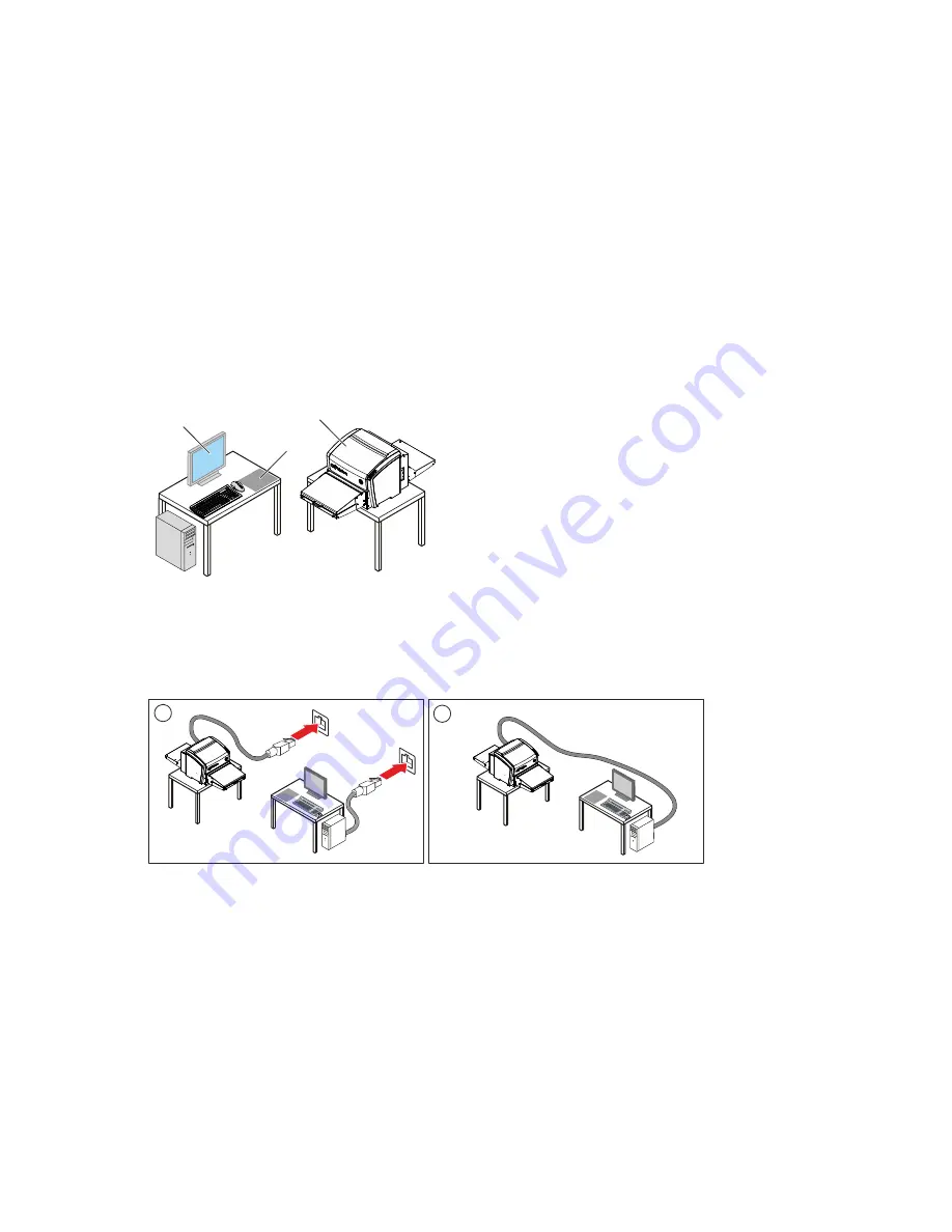
The system consists of: 

The CRxVision with  

  Optional input table / output table (each 43 cm) with light protection cover. 

  Optional input / output table (150 cm) 

Image plates - following types are available: 

  IPU for CRxVision 

  IPS for CRxVision 

  IPS2 for CRxVision 

  IPC2 for CRxVision 

Workstation for image processing and identification. 


1

2

3


The data transmission is performed via network. 
Two configurations are possible: 

Via local network 

Via point-to-point network connection 


1

2


CRxVision Operating Manual V1.2 

11


Summary of Contents for CRxVision

Page 1: ...GE Measurement Control Technologies Computed Radiography CRxVision CRxVision Operating Manual V1 2 LL ID 42124462 ...

Page 2: ...Table of Contents 2 CRxVision Operating Manual V1 2 ...

Page 3: ...ty 15 Electromagnetic Compatibility 15 Environmental Compliance 16 Equipment Classification 16 Connectivity 16 Training 16 Installation 17 Labels 20 Safety Instructions for Laser Products 21 Cleaning of the CRxVision 21 Cleaning of Image Plates 22 Preventive Maintenance 22 Quality Control 22 Environmental Protection 23 Safety Directions 24 General safety instructions 25 4 Getting started with the ...

Page 4: ...es 33 Re erasing an Image Plate 34 Cleaning the Optics Unit 35 Troubleshooting 38 Digitizer Remote Display 38 Connection Problems 38 Removing a jammed image plate 39 6 Technical Specifications 42 CRxVision 42 Image Plates 45 4 CRxVision Operating Manual V1 2 ...

Page 5: ...1 Revision History CRxVision Operating Manual V1 2 5 ...

Page 6: ...ersion Date Changes 1 0 2013 10 18 Initial version 1 1 2013 10 30 Changes after certification 1 2 2013 11 07 Adaptations due to new screw type for user accessible parts 6 CRxVision Operating Manual V1 2 ...

Page 7: ...2 Introduction to this Manual CRxVision Operating Manual V1 2 7 ...

Page 8: ...r person or can lead to a wrong inspection result The purpose of safety icons is to indicate at a glance the type of caution warning or danger Magnetic Field Hot Surface Laser Beam Ionizing Radiation Obstacles High Voltage Corrosive Liquid Explosive Material Caution Cautions are directions which if they are not followed can cause damage to the equipment described in this manual or any other equipm...

Page 9: ...ear in this document To improve reliability function or design GE reserves the right to change the product without further notice This manual is provided without warranty of any kind implied or expressed including but not limited to the implied warranties of merchantability and fitness for a particular purpose Technical Support For technical support contact your dealer a local customer support cen...

Page 10: ...able for CRxVision status and error messages NOTE In case of a usage different to the intended use the provided safeguards may be reduced in their effectiveness Intended User This manual has been written for trained users of GE computed radiography products and trained X Ray personnel who have received proper training Users are those persons who actually handle the equipment and those who have aut...

Page 11: ...50 cm 2 Image plates following types are available IPU for CRxVision IPS for CRxVision IPS2 for CRxVision IPC2 for CRxVision 3 Workstation for image processing and identification 1 2 3 The data transmission is performed via network Two configurations are possible 1 Via local network 2 Via point to point network connection 1 2 CRxVision Operating Manual V1 2 11 ...

Page 12: ...e type Image plate type Characteristics Application IPU for CRxVision Small particle size Phosphor Blue pigment in Phosphor layer and topcoat High resolution imaging IPS for CRxVision Small particle size Phosphor Coated topcoat Medium resolution imaging IPS2 for CRxVision Small particle size Phosphor Coated topcoat Medium resolution imaging IPC2 for CRxVision Large particle size Phosphor Screen pr...

Page 13: ...ion Controls The CRxVision interfaces with the user via 1 The Power Button 2 The Erase Button 3 The Status Indicator 4 The Digitizer Remote Display for CRxVision status and error messages 5 The Rhythm RT or Rhythm RT Lite graphical user interface 1 2 3 4 5 CRxVision Operating Manual V1 2 13 ...

Page 14: ...ning is not possible due to Service intervention is required or Service function which blocks scanning is called up by the field service engineer Slow red blinking 1 sec Boot up or Stand by mode or CRxVision warning or non fatal error Scanning is not possible due to User has to wait until boot up is finished or User has to initiate the scanning or erasing of an image plate or User intervention is ...

Page 15: ...part or signal output part configures a system and is therefore responsible that the system complies with the requirements of the valid version of the system standard If in doubt consult your local service organization Compliance General The product has been designed in accordance to DIRECTIVE 2006 95 EC Low Voltage Directive and DIRECTIVE 2004 108 EC Electromagnetic Compatibility of the EUROPEAN ...

Page 16: ... and Cleaning of Image Plates Operation Continuous operation Connectivity The CRxVision is connected to the workstation via network connection and uses the DICOM protocol to communicate with the workstation Training The user must have received adequate training on the safe and effective use of the product before attempting to work with it Training requirements may vary from country to country The ...

Page 17: ...he CRxVision is a tabletop digitizer The structure and stability of the table used need to be suitable in relation with the size and weight of the system The table should not be subject to excessive shock and vibrations from other sources as this may influence the image quality Warning Reduced image quality possible due to ambient light Operate the CRxVision in a dark room Warning The CRxVision is...

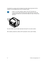
Page 18: ...d in the rear of the CRxVision For two persons to lift the CRxVision each should stand at the side of the CRxVision and hold it with one hand at the handle the other in the rear at the side cover Recommendation Keep the original packing for transport from one site to another After unpacking compare the delivery with the packing list which is part of delivery 18 CRxVision Operating Manual V1 2 ...

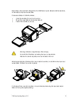
Page 19: ... 3 1 2 4 3 Warning CRxVision may fall down Risk of injury Do not lift the CRxVision by holding the input or output table Observe the center of gravity which is located in the rear When transporting the CRxVision from one location to another do not lift it at the input and output tables Observe the center of gravity For transport from one site to another it is recommended removing the input and out...

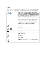
Page 20: ...Consideration relating to the choice of accessory equipment shall include Evidence that the safety certification of the accessory equipment has been performed in accordance with the appropriate harmonized national standard The party that makes the connections acts as system configurator and is responsible for complying with the systems standard If required contact your local service organization I...

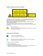
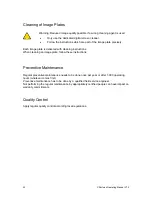
Page 21: ...f before removing the input unit or opening the back of the CRxVision Warning Risk of injury User interventions other than those described in this manual can be hazardous with regard to laser radiation Cleaning of the CRxVision Caution Device damage possible Make sure no liquid gets in the CRxVision Note Do not open the CRxVision for cleaning No components inside the CRxVision require cleaning by ...

Page 22: ...ning an image plate follow these instructions Preventive Maintenance Regular preventive maintenance needs to be done once per year or after 1 000 operating hours whatever comes first Preventive maintenance has to be done by a qualified field service engineer Not performing the regular maintenance by appropriately certified people can have impact on warranty commitments Quality Control Apply regula...

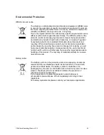
Page 23: ...n and or dealer By ensuring this product is disposed of correctly you will help prevent potential negative consequences for the environment and human health which could otherwise be caused by inappropriate waste handling of this product The recycling of materials will help to conserve natural resources Battery notice Li The battery symbol on the products and or accompanying documents means that th...

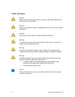
Page 24: ...with protective earth Warning The user is responsible for judging image quality and controlling ambient conditions when viewing printed or softcopy images for inspection purposes Warning The following actions may lead to serious risk of injury and damage to the equipment as well as making the warranty void Changes additions or maintenance to the product carried out by persons without appropriate q...

Page 25: ...rride or disconnect the integrated safety features Do not apply excessive shock or vibration to the CRxVision during operation This may decrease the image quality Neither should the CRxVision be moved during operation Do not allow the CRxVision to be subject to excessive vibration during operation due to unstable ground e g vibration of nearby equipment or footsteps Switch off the CRxVision before...

Page 26: ...4 Getting started with the CRxVision 26 CRxVision Operating Manual V1 2 ...

Page 27: ... The Digitizer Remote Display dialog contains information about the status of the digitizer 1 2 3 4 5 1 Status or error message 2 Status or error code 3 Date and time of the message 4 Button to confirm the message 5 Connection status and IP address Note The connection status is either connected or offline Starting Rhythm RT 1 Start Rhythm RT and select CRxVision from the available scanner pull dow...

Page 28: ...ision starts the following sequence Initialization of all components Functional test of all components Check for presence of image plates Establish connection to the workstation During the self test which takes approx 1 minute the CRxVision status indicator is blinking red Note During the self test you cannot activate any function If the CRxVision has completed the self test successfully the CRxVi...

Page 29: ...entered image plate 3 Press the scan button 4 Check that the CRxVision is ready for operation The status indicator on the CRxVision constantly lights up in green 5 Put the image plate on the table with the white IPS IPS2 IPC2 for CRxVision or blue IPU for CRxVision side facing up 6 Push the image plate towards the right alignment bar A 7 Push the image plate into the CRxVision until the magnetic s...

Page 30: ...d in the list to the left If more cropping areas are desired please select the Add button and an ROI will be added to the viewport that can be moved and sized as necessary ROI s that are not correctly placed can also be removed from the image by selecting the Delete button DICONDE tag management is done on a per ROI basis unless there are no ROI s positioned in which case they are just applied to ...

Page 31: ... plate the status indicator is blinking green Switching Off It is recommended to switch off the CRxVision at the end of the day To switch off press the power button POWER Note After switch off the CRxVision is still in stand by mode To remove the CRxVision from the mains supply disconnect the mains plug CRxVision Operating Manual V1 2 31 ...

Page 32: ...5 Operating the CRxVision 32 CRxVision Operating Manual V1 2 ...

Page 33: ...e status indicator is green flashing 2 Wait until the status indicator is green Now for a time interval of 15 seconds another image plate can be entered with the same identification data than the previous scanned image plate 3 Enter the next image plate 2 1 2 Entering image plates in sequential order may lead to reduced image quality To scan multiple image plates in parallel proceed as follows 1 P...

Page 34: ... button at the front side The status indicator is continuously lighting up in blue If within one minute no image plate is entered the CRxVision returns to the standby mode 3 Put the image plate on the input table with the white IPS IPS2 IPC2 for CRxVision or blue IPU for CRxVision side facing up 4 Align the image plate with the alignment bar A and push it into the CRxVision B until the magnetic sc...

Page 35: ... you recognize this type of artifact when using the CRxVision clean the optic unit using the cleaning brush To clean the optic unit proceed as follows 1 Switch off the CRxVision A 2 Disconnect the network cable B 3 Disconnect the power cable C 4 Turn the handle D 5 Remove the input table E A POWER E D C B CRxVision Operating Manual V1 2 35 ...

Page 36: ... the cable G 9 Remove the input unit F F G Caution Damage of the image plate possible if cleaning brush is not in its home position Always drive back the cleaning brush to the home position 10 Using the medium size Phillips screwdriver drive the cleaning brush to its end position and back again 36 CRxVision Operating Manual V1 2 ...

Page 37: ... the CRxVision in reverse order Note When mounting the Input Unit take care to insert the two flaps into the frame 12 Verify the re mounting by scanning an unexposed image plate CRxVision Operating Manual V1 2 37 ...

Page 38: ...tatus indicator of the CRxVision is blinking red the user should look at the status of the Digitizer Remote Display to decide whether CRxVision internal problems or connection problems occurred If an error message is displayed on the acquisition station the user is informed which actions to perform to solve the problem In case no error message is displayed on the screen a connection problem occurr...

Page 39: ...lows 1 Switch off the CRxVision A 2 Disconnect the network cable B 3 Disconnect the power cable C 4 Turn the handle D 5 Remove the output table E A POWER C E D B 6 Using a medium size Phillips screwdriver remove the screws for the rear cover CRxVision Operating Manual V1 2 39 ...

Page 40: ...a few centimeters 11 Disconnect three connectors Warning During operation the Erasure Unit is hot Risk of burns Avoid contact with the Erasure Unit Observe the relevant sticker on the Erasure Unit 12 Pull out the IP Transport Unit with Erasure Unit Erasure Unit IP Transport Unit 40 CRxVision Operating Manual V1 2 ...

Page 41: ...anization Make sure not to bend the image plate excessively when removing it from the CRxVision After a jam the image plate can be used again if it is not damaged After removing a jammed image plate erase the image plate before the next exposure 14 Mount in reverse order 15 Verify the re mounting by scanning an unexposed image plate CRxVision Operating Manual V1 2 41 ...

Page 42: ... name CRxVision Model number 5177 100 Original equipment manufacturer Agfa HealthCare N V Mortsel Belgium Labeling CE cNRTLus KC C Tick EAC Dimensions 132 0 cm 47 6 cm 44 9 cm 39 5 cm 46 9 cm 53 8 cm 57 9 cm 46 2 cm 45 9 cm 46 1 cm 36 6 cm 36 6 cm 53 8 cm 42 CRxVision Operating Manual V1 2 ...

Page 43: ...A Mains fuse protection Europe min 10 A max 16 A USA Japan min 10 A max 15 A Digitizer input voltage current 24 V DC max 6 25 A Network connectivity Ethernet connector RJ45 female 10 100 Mbit s autosensing shielding CAT5 Power consumption Standby 110 V 240 V 50 60 Hz configuration max 22 W During operation 110 V 240 V 50 60 Hz configuration max 140 W Environmental conditions CRxVision during opera...

Page 44: ...nsport IEC 60721 3 2 1997 class 2M2 Physical emissions Heat emission standby Standby 22 W 75 BTU h Peak heat emission scanning 140 W 478 BTU h Scan speed High resolution 19 3 cm per minute Medium resolution 66 cm per minute End of life Estimated product life 7 years if regularly serviced and maintained according to service instructions 44 CRxVision Operating Manual V1 2 ...

Page 45: ...n Image Plate sizes Image plate width and length Width between 1 6 cm and 35 cm Length between 12 cm and 150 cm Image plate thickness 0 6 mm Environmental conditions Image Plate Scanning temperature recommended 20 C to 25 C allowed 15 C to 35 C Expose temperature 25 C to 55 C Relative humidity 10 85 Mechanical conditions for transport In packaging IEC 721 3 2 1997 class 2M2 Shock specifications In...

Reviews: